MACHINE SETTING AND USE
3.4
T1
BF-NGB3
3-2
3-2
3-2
3-2
3-2 MACHINE ST
MACHINE ST
MACHINE ST
MACHINE ST
MACHINE STAR
AR
AR
AR
ART
T
T
T
T
1) Make sure that:
-
the emergency buttons are released (otherwise turn them to the arrow direction)
-
the motor housing door is closed
-
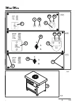
button A2 of main switch (A fig.3.4a) is pressed
-
the handle for spindle locking is on position corresponding to spindle unlocking.
2) PROFILING
make sure that:
-
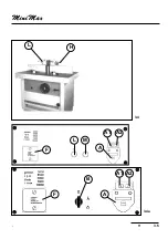
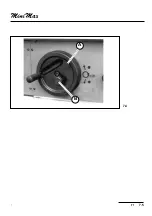
hood-fence unit (fig.3.4) is in the right position and clamped by handles (H-L)
-
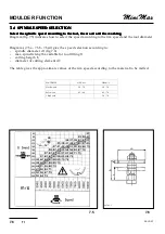
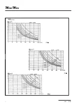
the speed on the display is proper for the tool (see par.7-4).
then:
-
turn change-over switch (B) to star position for starting the motor; then after some seconds turn
the change-over switch to delta position.
-
to stop the motor turn change-over switch (B) to 0.
-
Press button (M) to start the motor
-
Press button (L) to stop the motor
Summary of Contents for FORMULA T1
Page 22: ...T1 2 3 2 2 1 2 2 kg _____ 475 ...
Page 24: ...T1 2 5 2 2 6 2 5 B T13216 E D E K D C ...
Page 26: ...T1 2 7 2 MORSE1 L1 L2 L3 N PE P 2 7 ...
Page 29: ...INSTALLATION 2 10 T1 BF NGB2 ...
Page 32: ...T1 3 3 3 A1 A2 F L M A A1 A2 B A F B V V 3 1 P 3 2 ...
Page 34: ...T1 3 5 3 L H 3 4 A1 A2 F L M A A1 A2 B A F 3 4a ...
Page 35: ...MACHINE SETTING AND USE 3 6 T1 BF NGB3 ...
Page 38: ...T1 7 3 7 7 2 7 3 ALBE1 ALBE2 D B S A C B A Z T 7 1 A F P bf7 4 ...
Page 40: ...T1 7 5 7 B A 7 4 ...
Page 42: ...T1 7 7 7 7 6c 7 6a 7 6b ...
Page 44: ...T1 7 9 7 7 7 7 8 L S N C G P H ...
Page 46: ...T1 7 11 71 L H A M P C 7 9 ...
Page 48: ...T1 7 13 71 7 13 REGISTR M 7 12 H M P L I T F R ...
Page 50: ...T1 7 15 71 CUFFI4 F R 7 14 7 15 I T REGISTR M H M P L ...

