wwww.minisolarworld.com
●
3
MT-150 Assembling Guide
Assembling and Experiment steps
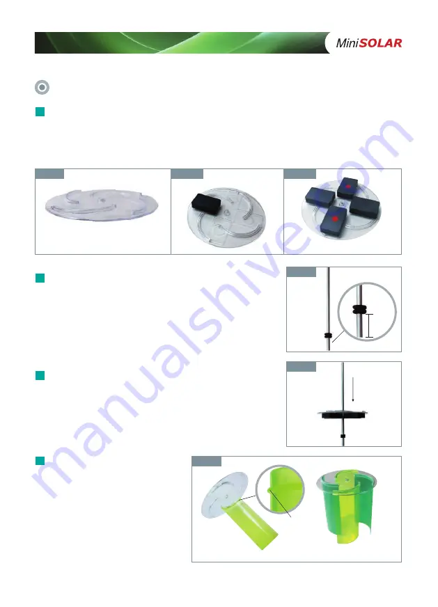
Put the rubber rings on the aluminum pipe (pivot)
Put the 2 rubber rings on the aluminum pipe (pivot, component
#10) with a distance 1-2cm from the bottom, refer to <Fig. 2>.
※ The distance from the bottom can affect the performance
of generator.
2
Top and Bottom of Lower Plate
↑
Bottom
N
N
S
S
↓
Top
Plate with Magnets
<Fig. 2>
Insert the pipe thru the hole in the center of lower plate
till the rings.
The bottom with magnets faces the rings, refer to <Fig. 3>.
3
<Fig. 3>
Fix the wings to upper plate
(component #4).
Upper plate has 4 furrows to fix the
wings. Fix the wings to the plate
using the side with sill.
※ Be careful not to fix the wings
with wrong side, refer to <Fig. 1-a>
to see the difference between
upper plate and lower plate.
4
<Fig. 4>
<Fig. 4-1>
Sill of the Wing
<Fig. 4-2> Upper Plate with 4 Wings
1~2cm
↘
2 Rubber
Rings
<Fig. 1-1>
<Fig. 1-2>
<Fig. 1-3>
Fix the magnets to lower plate.
Fix the 4 magnets at the prepared places on the bottom of the
‘lower plate’(component #3) using
double-sided tape, refer to <Fig. 1>.
Keep the sequence of magnet’
s polarity, N-S-N-S, refer to <Fig. 1-c>.
(The side with red spot is S polarity of the magnets)
1
Summary of Contents for MT-150
Page 8: ...www minisolarworld com ...


