background image

Manual design and all elements of manual design are protected by U.S. Federal and/or State Law, including Patent, Trademark and/or Copyright laws.

Summary of Contents for Bolo

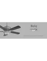
Page 1: ...INSTRUCTION MANUAL WARRANTY CERTIFICATE Bolo BY TM...

Page 2: ...Manual design and all elements of manual design are protected by U S Federal and or State Law including Patent Trademark and or Copyright laws...

Page 3: ...arranty service the owner should return the fan along with proof of purchase to a Minka Aire authorized dealer The Minka Aire authorized dealer shall then at its sole discretion repair the fan replace...

Page 4: ...costs This limited warranty is in lieu of all other express warranties This limited warranty excludes all incidental and consequential damages and Minka Aire shall not under any circumstances be liab...

Page 5: ...TE CONTROL WALL CONTROL CARE OF YOUR FAN TROUBLESHOOTING SPECIFICATIONS 1 2 3 4 5 6 7 8 9 10 11 12 13 14 15 UL LISTED E75795 R 1151 W Bradford Court Corona CA 92882 For Customer Assistance Call 1 800...

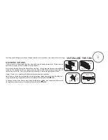
Page 6: ...l 5 If you are mounting the fan to a ceiling fan outlet box use a U L Listed metal octagonal outlet box marked Acceptable for Fan Support Secure the box directly to the building structure The outlet b...

Page 7: ...CLEANING THE FAN DO NOT INSERT FOREIGN OBJECTS BETWEEN ROTATING FAN BLADES TO REDUCE THE RISK OF FIRE OR ELECTRIC SHOCK DO NOT USE THIS WITH ANY SOLID STATE SPEED CONTROL DEVICE NOTE The important saf...

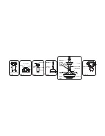
Page 8: ...13 5mm Screws with lock washers 11 PCs PACKAGE CONTENTS 3 4 1 2 5a 5b 11 12 13 16 15 14 10 6 7 7 8 9 A B C Unpack your fan and check the contents You should have the following items 1 Fan blades 5 2 H...

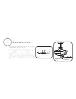
Page 9: ...astic outlet box Figure 1 2 and 3 are examples of different ways to mount the outlet box Note You may need a longer downrod to maintain proper blade clearance when installing on a steep sloped ceiling...

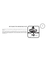
Page 10: ...embly Fig 6 Step 3 Remove the Hanger Ball from the Downrod Assembly by loosening the Set Screw and removing the Cross Pin Fig 7 Step 4 Carefully feed fan wires up through the downrod Fig 8 Thread Down...

Page 11: ...ig 5 Fig 7 Fig 8 Fig 6 Fig 10 REGISTRATION SLOT CROSS PIN HANGER BALL DOWNROD HITCH PIN LOCK PIN SET SCREWS SET SCREW Fig 9 DOWNROD CANOPY CANOPY COVER SET SCREWS HITCH PIN LOCK PIN COUPLING OMIT COUP...

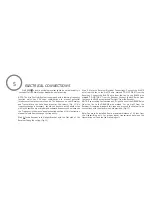
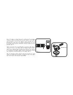
Page 12: ...ceiver into Hanger Bracket with the flat side of the Receiver facing the ceiling Fig 12 Step 2 Motor to Receiver Electrical Connections Connect the WHITE wire from the fan to the WHITE wire marked TO...

Page 13: ...p 4 If your outlet box has a GROUND wire Green or Bare Copper connect this wire to the Hanger Ball and Hanger Bracket Ground wires If your outlet box does not have a Ground Wire then connect the Hange...

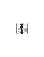
Page 14: ...WHITE AC IN N WHITE TO MOTOR N GROUND GREEN CONNECT TO GROUND WIRE ON HANGER BRACKE IF NO HOUSE GROUND WIRE EXISTS OUTLET BOX BLACK HOT BLACK AC IN L BLACK TO MOTOR L RECEIVER BLUE FOR LIGHT BLUE FOR...

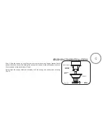
Page 15: ...acket Rotate canopy clockwise next while holding the canopy with one hand slide the canopy cover over the screws and rotate clockwise until tight Note Adjust the canopy screws as necessary until the c...

Page 16: ...r washers provided tighten screws securely Fig 15 Step 2 Remove rubber stops from motor Rotate motor so that the screw holes are revealed through the opening on switch cap plate Align motor holes to b...

Page 17: ...es from the mounting plate over the 2 screws previously loosened from the mounting ring turn mounting plate until it locks in place at the narrow section of the key holes Secure by tightening the 2 sc...

Page 18: ...p 1 Remove the 3 screws from the mounting plate Step 2 Place the light kit attached close to the mounting plate firmly snap the wire molex together Fig 18 Step 3 Carefully place the light kit assembly...

Page 19: ...tive nut from the light kit Place the rubber washer glass shade rubber washer and metal washers over the light kit stem Place the nut over the stem and turn it clockwise until it locks up against the...

Page 20: ...2 Attach the plug to the switch housing Fig 21 3 Holding the switch housing under your fan snap together the wire connection plugs 4 Install the switch housing to the mounting plate with screws provi...

Page 21: ...n to set the desired light brightness The light will cycle between bright and dim settings as long as the button is pressed The light key has an automatic auto resume feature that allows the light to...

Page 22: ...Weather forward A DOWNWARD airflow creates a cooling effect as shown in Figure 22 This allows you to set your air conditioner on a warmer setting without affecting your comfort Cool Weather Reverse A...

Page 23: ...3 If your fan is provided with wood veneer blades you can apply a light coat of furniture polish for additional protection and enhanced beauty Cover small scratches with a light application of shoe po...

Page 24: ...f 40 feet from the transmitting unit for proper signal transmission between the transmitting unit and the fan s receiving unit SOLUTION SYMPTOM Fan Sounds Noisy Allow a 24 hour break in period Most no...

Page 25: ...ed if the wobble is excessive follow instructions included with balancing kit SOLUTION SYMPTOM Fans Light Turn On and Off Unexpectedly This is caused by interference Please see Frequency interference...

Page 26: ...s AC power ON Press the transmitter s Stop button and hold the Stop button for 10 seconds Once the receiver has detected the set frequency the down light of your fan if applicable will blink twice th...

Page 27: ...Your actual fan may vary They do not include amps and wattage used by the light s For any additional information about your Minka Aire Ceiling fan please write to R 1151 W Bradford Court Corona CA 928...

Reviews: