background image

66

TONE CURVES AND HISTOGRAM

CORRECTING THE TONE CURVES

Changing the shape of a correction curve changes the output
level for each corresponding input level. Changing the shape
of the red, green, or blue curves affects color balance of the
image. Changes to the RGB curve affect the image contrast
and brightness.

1.

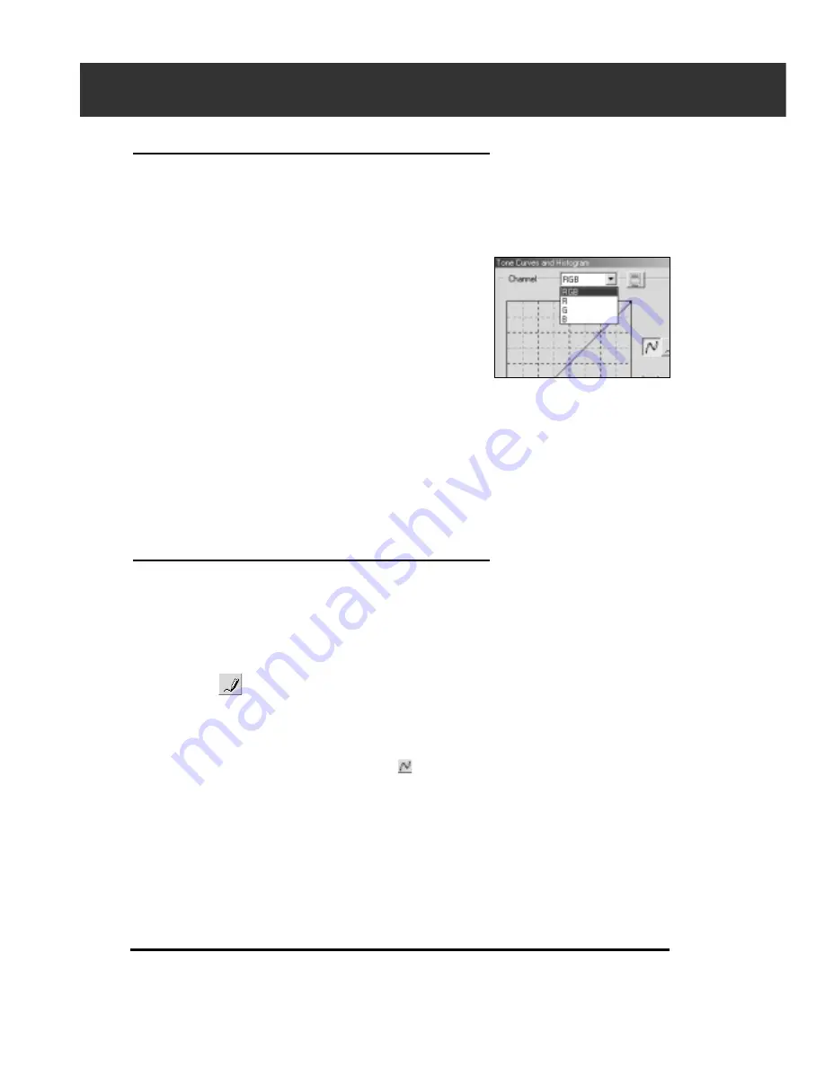
Click on the arrow next to the channel to display
the available channel (RGB, R, G, B).

2.

Select the channel of the color to be corrected.

3.

Click and drag the portion of the curve to be
changed.

• The coordinate value of the cursor is displayed from 0 to

255.

• The corrected image by changing the tone curves is

applied to the prescan image.

• You can also change the tone curves by freehand.

CHANGING THE TONE CURVES BY FREEHAND

This function allows you to draw tone curves by freehand.

1.

Select the channel of the color (R, G, B, RGB) to
be corrected from the channel selection menu.

2.

Click on 

.

• The cursor changes to the pencil shape.

3.

Draw the desired curve by dragging.

• To smooth out the curve points, click on 

.

• The change will be reflected in the prescan image.

Summary of Contents for DiMAGE Scan Multi PRO AF-5000

Page 1: ...E INSTRUCTION MANUAL 9224 2887 11 H A107 ...

Page 2: ...TM and Digital GEMTM are trademarks of registered trademarks and techenolgies of Applied Science Fiction Inc in U S A Other corporate and product names are the trademarks and registered trademarks of their respective companies Changes or modifications not approved by the party responsible for compliance could void the user s authority to operate the equipment This manual may not be copied in part ...

Page 3: ...tal objects such as paper clips or staples into this product It may cause damage or injury through fire or electric shock Discontinue use if an object enters the product Do not use the product near inflammable gases or liquids such as gasoline benzine or paint thinner Do not use inflammable products such as alcohol benzine or paint thinner to clean the product The use of inflammable cleaners and s...

Page 4: ...film attachments with glass and glassless Film Masks Ultra SCSI D sub half pitch 50 pin connector cable IEEE1394 connector cable AC power cord CD ROM for DiMAGE Scan Multi PRO software Warranty card and Instruction Manual 4 PACKAGE CONTENTS THE FOLLOWING CONTENTS SHOULD BE INCLUDED IN THIS PACKAGE Shape of plug varies with destination ...

Page 5: ...stem and the names of the parts This section describes how to set up the scanner Final Scan 10 13 This section describes how to perform the index scan 41 This section describes how to perform the preview scan 49 This section describes how to perform the final scan and save it 63 Read this section if necessary 91 105 This section describes how to perform the image correction ...

Page 6: ... LAUNCHING THE SOFTWARE WINDOW 26 Launching the TWAIN Drivers 26 Launching the Utility Software 26 LAUNCHING THE SOFTWARE MACINTOSH 27 Launching the Plug in 27 Launching the Utility Software 27 MAIN WINDOW MAIN WINDOW 28 The Main Window Part Names of Parts 28 SETTING THE PREFERENCES 29 LOADING THE FILM HOLDER 31 35mm Film Holder FH P1 31 Slide Mount Holder SH P1 32 Loading the Universal Holder UH ...

Page 7: ...INDEX IMAGE FILE 47 LOADING THE INDEX IMAGE FILE 48 PREVIEW SCAN PRESCAN WINDOW 50 The Prescan Tab Part Names of Parts 50 MAKING A PRESCAN 51 ROTATING THE IMAGE 52 FLIPPING THE IMAGE 53 FULL SCREEN VIEWING MAGNIFYING OR REDUCING THE VIEW 54 Full Screen View 54 Magnifying or Reducing the View 54 SCROLLING THE IMAGE 55 AUTO EXPOSURE LOCK 56 Setting the AE Lock 56 Cancelling the AE Lock 56 AE AREA LO...

Page 8: ...f Parts 72 Auto Setting 73 Reset 73 VARIATION CORRECTION 74 The Variation Dialog Box Names of Parts 74 Selecting the Correction Item 74 Changing the Amount of Correction Step 74 Color Balance Correction 75 Brightness Contrast Correction 75 Saturation Correction 76 Reset 76 SELECTIVE COLOR CORRECTION 77 The Selective Color Correction Dialog Box Names of Parts 77 Reset 77 UNSHARP MASK 78 The Unsharp...

Page 9: ...iver Plug in Software 98 Utility Software 99 CUSTOM WIZARD 100 When starting a registered setting 104 APPENDIX IEEE 1394 INTERFACE 106 COLOR MATCHING 107 Output Color Space Setting 108 ICC Profile Setting 108 SCAN JOB FILE LIST 35 mm 110 SCAN JOB FILE LIST 120 220 6X4 5 112 SCAN JOB FILE LIST 120 220 6X6 114 SCAN JOB FILE LIST 120 220 6X7 116 SCAN JOB FILE LIST 120 220 6X8 118 SCAN JOB FILE LIST 1...

Page 10: ...e hard disk space About 6 GB or more of available hard disk space when scanning with 16 bit output or using the Digital ICE ROC GEM functions 8 GB or more is recommended Recommended Board Adaptec SCSI CARD 19160 SCSI CARD 29160 SCSI CARD 29160N Adaptec Fireconnect 4300 PROCOMP SpeedDemon 400P OHCI compatible IEEE 1394 port 3 as standard interface SCSI IEEE 1394 Support cannot be provided for custo...

Page 11: ...02 Ver 5 5 and Ver 6 0 Photoshop 5 0LE About 2GB or more of available hard disk space About 6 GB or more of available hard disk space when loading with 16 bit or using the Digital ICE ROC GEM functions About 8 GB or more is recommended Adaptec PowerDomain 29160N PowerDomain 2930U PowerDomain 2940UW PowerDomain 2940U2W 1024 x 768 pixels is recommended 640 x 480 pixels can be used Capable of display...

Page 12: ...12 SCANNER NAMES OF PARTS Film slot door Indicator lamp Film Holder Eject button Power switch SCSI ID switch IEEE 1394 interface connector Dip switch AC power socket SCSI Interface connector ...

Page 13: ...CONNECTING THE HARDWARE REMOVING THE OPTICS LOCKING SCREW LAUNCHING THE SOFTWARE INSTALLING THE SOFTWARE SETTING THE FILM FORMAT FILM TYPE SETTING THE PREFERENCES INSERTING THE FILM HOLDER LOADING THE FILM HOLDER GETTING STARTED USING THE SCSI INTERFACE USING THE IEEE1394 INTERFACE ...

Page 14: ...the optics to the locking position to prevent a damage and then tighten the optics locking screw on the bottom panel of the scanner 1 When the DiMAGE Scan Multi PRO Utility Software is in function Windows Press Ctrl Shift and L key simultaneously Macintosh Press Command Shift and L key simultaneously 2 When The optics will be moved to the locked position appears on the screen click on OK 3 The opt...

Page 15: ...as the interface that is used to connect the scanner to a computer If this scanner is the terminal device of the SCSI chain set to ON The switch No 1 is factory preset to ON Switch No 2 Auto Power Save Set to ON up if you want the fluorescent light to turn off automatically when you are not going to use it for about 2 hours In order to save electricity and the life of the fluorescent light we reco...

Page 16: ...ces in the same SCSI chain cannot share a SCSI ID A SCSI ID is a unique address you assign to each SCSI device connected to your computer The SCSI ID range of your computer is from 0 to 7 however some ID s are already occupied IBM PC AT Macintosh Occupied SCSI ID 7 SCSI host adapter 0 internal hard drive 3 internal CD ROM drive 7 operating system IDE Macintosh systems do not use SCSI ID 0 for the ...

Page 17: ... SCSI cable to either SCSI port on the back of the scanner Either SCSI port can be used for other configurations there is no dedicated in or out port 3 Connect the other end of the SCSI cable to the SCSI port on the computer or the last device in the SCSI chain Connecting the SCSI Cable This scanner has been packaged with the SCSI cable SC P1 See your dealer if you require a different SCSI cable T...

Page 18: ...E SCSI INTERFACE Terminating the SCSI chain helps to suppress electronic noise in the SCSI chain Not terminating the SCSI chain can cause slowdowns data errors crashes and other unpredictable errors This device is to be used with a power source within the voltage as specified on the back of unit 6 Plug the power cord into the scanner s AC socket then plug it into a grounded outlet This device is t...

Page 19: ...ed FireWire Example Connect the IEEE 1394 Hub terminal 1 Turn the SCSI terminator switch Dip switch 4 to OFF 2 Connect one end of the IEEE 1394 cable to either IEEE 1394 port on the back of the scanner The maximum number of equipment you can connect to this terminal is 63 However if you use a daisy chain it is 16 Before connecting the IEEE1394 Interface unit to a personal computer install the driv...

Page 20: ...1 Turn on the computer to start Windows 2 Insert the DiMAGE Scan Multi PRO CD ROM into the CD ROM drive In a little while a splash screen for Setup will appear 3 Click on Starting up the DiMAGE Scan Multi PRO installer In a little while the program decompression screen will appear followed by the InstallShield Wizard program screen after that the program will start automatically To confirm the con...

Page 21: ...ositioned at D Driver English Setup exe and click OK In a little while a splash screen for Setup will appear After that continue to step 4 The drive name will differ depending on the System preference you are using 4 Click on The start Setup window and License Agreement window appears Read the entire agreement carefully before continuing the setup If you don t agree to the terms of the License Agr...

Page 22: ...f the descriptions in this manual assume the Twain data source setup has been selected Click Next to display the window for selecting the Program Folder 8 The name of the default Program Folder is displayed in reverse To add the software icons to this folder click To add the software icons to another existing folder select it from the folders listed in the box below Existing Folders then click Nex...

Page 23: ...ions Continued on the following page 1 Turn on the DiMAGE Scan Multi PRO 2 Turn on the Macintosh and start up the Mac OS 3 Insert the DiMAGE Scan Multi PRO CD ROM into the CD ROM drive Dimage Scan Multi PRO will appear on the desktop 4 Double click on DiMAGE Scan Multi PRO The driver folders will appear 5 Double click on Driver folder The language folders will appear 6 Open the English language fo...

Page 24: ...cline and the software will not be installed 9 Check the folder in which the software will be installed To change it select Select folder from the Install Location pop up menu then select an existing folder or create a new one 10 Select the installation method from the pop up menu at the top left Normally you don t need to change the installation method from Easy Install If you select Custom Insta...

Page 25: ...w folder titled DiMAGE Scan Multi PRO If Easy Install was chosen the DiMAGE Scan Multi PRO folder will contain the following items DS_MultiPRO Utility DS_MultiPRO Plug in and Read Me file 13 Drag the DS Multi PRO Plug in to the Import Export folder in the Adobe Photoshop Plug ins folder Your Macintosh will restart INSTALLING THE SOFTWARE MACINTOSH ...

Page 26: ... the software through another application such as your image editing software LAUNCHING THE TWAIN DRIVER This manual uses Adobe Photoshop Ver 6 0 as the host application Commands may vary among applications 1 Open the host application 2 Select File Import DS_MultiPRO1 0 For Adobe Photoshop Ver 5 to 5 5 not Ver 6 1 Select File Import Select TWAIN_32 Source 2 Select DS_MultiPRO 1 0 then click on Sel...

Page 27: ...e Photoshop Ver 6 0 as the host application Commands may vary among applications 1 Launch Adobe Photoshop 2 Select File Import DS_MultiPRO Plug in The software is ready for use when the Main window appears page 28 LAUNCHING THE UTILITY SOFTWARE Use the utility software as a stand alone application when you just want to scan the photographic image and store 1 Double click on ...

Page 28: ... see page 63 Scan Setting part see page 92 Main Window part see below Holder Type list box Film format list box Index Scan button Prescan button Scan button Film Type list box Preferences button Close button Status display area Custom wizard button Help button on Macintosh Digital GEM button Digital ROC button Digital ICE button Eject button ...

Page 29: ...setting The checkmark is not on the checkbox However if you intend to use the Autofocus function when scanning click on the checkbox of Auto Focus at Scan When using the Digital ICE ROC or Digital GEM function see page 85 it is recommended to turn on the Autofocus function by clicking on the checkbox of Auto Focus at Scan Close Driver After Scanning checkbox This option allows you to select whethe...

Page 30: ...4 times 8 times Perform sampling 8 times 16 times Perform sampling 16 times The more times the image is sampled the longer the required time for scanning Preview Size selecting list box Select the display size of prescan image The default setting is Small Large A prescan image is displayed in its original size Small A prescan image is displayed in the reduced size Index Scan priority select the ra...

Page 31: ...pen the slide holder by pulling up the tab from underneath 2 Place the film in the film holder emulsion side down Make sure the film strip is under the two nouches at the top of the holder 3 Align the frames within the scanning windows 4 Close the cover and press firmly until it clicks LOADING THE FILM HOLDER The three types of holders are supplied with this scanner Select the appropriate one acco...

Page 32: ...then open the slide mount Open the slide holder by pulling up the tab from underneath 2 Place the slides within the indentations making sure they lie flat Insert the slides emulsion side down 3 Press the cover firmly closed until it clicks With the fourth frame of the slide mount holder you can change slides without removing the slide mount holder from the scanner A prescan should be made with eac...

Page 33: ...ent with that of mask and fix the two protruding parts on the upper side and the film guide of the mask to the attachment and then fit the holes on the pins of the attachment LOADING THE UNIVERSAL HOLDER UH P1 The universal holder UH P1 is used with the following attachments Use the attachment suited to the film 120 220 film attachment with glass HA P1 glassless HA P2 When scanning 120 220 6x4 5 6...

Page 34: ...lm While pressing the button on the lower side of the attachment lift the film cover Removing an Attachment While sliding the lever on the middle part of the holder to the right lift the attachment 4 Place a film on the mask with the emulsion side down while aligning the lower side of the film with the film guide at the upper or lower side 5 Close the film cover of the holder until it clicks LOADI...

Page 35: ...he film to the right side of the frame The scanning position will be determined by the film format selected on the main window Adjust the slide bar to determine the mounting position of the left side of the film There are white markings on the slide bar one on the bottom of the attachment and in two places on the cover Set the position using these markings 4 Place the film on to the attachment emu...

Page 36: ...f the 120 220 film attachment with glass HA P1 or glassless HA P2 is installed remove it beforehand 2 Fit the two pins on the upper side of the film cover into the holes on the upper side of the holder until they click 36 3 Make the appropriate mask that is suited for the size of the film When making a mask cut out the sheet with a cutter etc using the scales drawn on the mask as a guide to a size...

Page 37: ...he cover and remove the pins 2 While sliding the lever on the middle part of the holder to the right lift the attachment 5 Place a film on the mask with the emulsion side down while aligning the lower side of the film with the film guide at the upper or lower side 6 Close the film cover of the holder until it clicks Be sure to place the appropriate mask and then place a film when scanning Otherwis...

Page 38: ...lder at an angle 3 Gently push the holder into the scanner until the raised insertion mark is aligned with the film slot door The film holder will be automatically guided in past the mark If the holder is not loaded correctly then eject and reinsert it Please take note that depending on the type of film holder the position of this indicator will differ Ejecting 1 Press the film folder eject button...

Page 39: ... formats and appropriate holders for scanning Selecting the Holder Type When 6x4 5 6x6 6x7 6x8 or 6x9 is selected in the film format select the holder type 1 Select the holder type from the drop down list in the main window The available holder types are with Glasses or Glassless Film format Holder type 35mm 35 mm film holder FH P1 or Slide mount holder SH P1 6x4 5 6x6 6x7 6x8 6x9 Multi Format 35m...

Page 40: ...e 120 220 35mm Full panorama 6 x 4 5 6 x 6 6 x 7 6 x 8 6 x 9 Type Sleeve Sleeve Sleeve Slide Slide with Glass Glassless Universal 120 220 Universal Multi format Holder type Multi format 35mm Multi format 6x9 APS Sleeve 16mm Sleeve Minox Sleeve 4 x 5 Aperture guard for 120 220 APS Cartridge Aperture guard For microfilm 59x81 5 Electron microscope 59x163 82x102 82x118 1 2 1 Possible to scan the enti...

Page 41: ...tating or Flipping the index frames Reversing frame order full scall view Saving the index scan image Saving the index image file Loading the index image file FINAL SCAN AND SAVE see page 98 Launch the Software see page 26 Set the Preferences see page 29 Load the Film Holder see page 31 Inserting the Film Holder see page 38 Setting the Film Format Film Type see page 39 ...

Page 42: ... appropriate image box in the index tab to select an image for prescanning or scanning There are two options for making an index scan are available Speed or Quality Select the desired option in the Preference dialog box see page 29 Click on Index tab in the Main window THE INDEX TAB PART NAMES OF PARTS Rotate left button Rotate right button Flip Horizontal button Flip Vertical button Full Scale Vi...

Page 43: ...d appear in the Index tab To cancel the index scan press the escape key Command and period for the Macintosh until the Cancelling Index Scan message box appears The completed index scans will appear in the Index tab Frames that have not been index scanned can still be selected for prescanning and scanning When the Full Screen View button is not clicked the size and shape of the index frames does n...

Page 44: ...e scans will be saved using the selected file name and numbered chronologically Example File_Name01 File_Name02 File_Name03 CLICK CLICK Not selected Click on to save the index as an image file see page 46 The image can be saved in JPEG or BMP format JPEG or PICT format for the Macintosh Press the control key key for the Macintosh while clicking to select additional frames for scanning Press the co...

Page 45: ...MES Rotate or Flip index frames so they appear in the Index scan tab window with the proper orientation REVERSING THE FRAME ORDER Some cameras are reverse winding so the last frame is exposed at the beginning of the roll The order of the Index tab can be reversed to correct the chronology 1 Click on FULL SCALE VIEW This function allows you to display the entry prescanned image in the Index tab 1 C...

Page 46: ...with the specified file name Windows For Windows the file can be saved in the Windows Bitmap BMP or JPEG format Macintosh For Macintosh the file can be saved in the PICT or JPEG format The index scan images are arranged in the image file to be saved as follows When there are 4 index frames the frames are arranged in 4 columns of one line When there are 6 columns of 2 limes A spacing of 50 pixels i...

Page 47: ...ter the desired file name select the file destination and then click on Save When the index images are displayed these images are saved regardless of the film set in the scanner When the index images are not displayed the index images are saved after performing the index scan If there are index images which have not been scanned yet those images will be scanned and then all index images including ...

Page 48: ...ile The previously displayed preview images are erased 1 Click on in the Main window The standard file open dialog box for each operating system will appear 2 Select the index file to be load and then click on Open When the previous index scan image is displayed the image is replaced with the current loaded image ...

Page 49: ...lock Auto cropping Cropping the Image Cropping the prescan image Focus Point AF auto focus Focus Manual Displaying frame number RGB CMY information IMAGE CORRECTION see page 63 INDEX SCAN see page 41 FINAL SCAN AND SAVE see page 98 Launch the Software see page 26 Set the Preferences see page 29 Load the Film Holder see page 31 Inserting the Film Holder see page 38 Setting the Film Format Film Type...

Page 50: ...the Scan button This ensures that final scan will be the best it can be Click on the Prescan tab in the Main window Rotate Left button Rotate Right button Flip Horizontal button Flip Vertical button Full Scale View button Zoom button Grab button Frame number indicator RGB CMY display Zoom prescan button Auto Cropping button Manual Focus button Point AF button AE Lock button AE Area Lock button ...

Page 51: ...GE Scan Multi PRO 51 1 Click on in the Main window The prescanned image will appear in the Prescan tab Press Ctrl when prescanning on the Macintosh to see CMY values in the RGB CMY display MAKING A PRESCAN ...

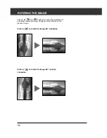
Page 52: ...E Click on the and buttons to correct the orientation of your image before scanning Changes will be reflected in the prescan image Click on to rotate the image 90 clockwise Click on to rotate the image 90 counter clockwise ...

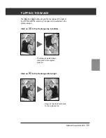
Page 53: ...e left to right or top to bottom before scanning Changes will be reflected in the prescan image Click on to flip the image top to bottom Click on to flip the image left to right The image is upside down compared to the original prescan Image is reversed compared to the original scan ...

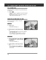
Page 54: ...In 1 Click on The pointer will change to 2 Click anywhere on the image to zoom in The clicked position will be the center of the magnified view in the Prescan tab The disappears from the magnifier icon when the maximum image magnification has been reached Zooming Out 1 Press and hold the Ctrl key option key on the Macintosh to reduce the image magnification The pointer will change to 2 Click anywh...

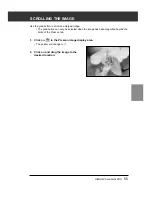
Page 55: ...rged image The grab button can only be selected when the image has been magnified beyond the limits of the Prescan tab SCROLLING THE IMAGE 1 Click on in the Prescan image display area The pointer will change to 2 Click on and drag the image to the desired location ...

Page 56: ... Preferences see page 29 and prescanning the color positive film SETTING THE AE LOCK After prescanning the image 1 Click on can not be selected until an image has been prescanned 2 Select another image then click on The locked exposure setting will apply to the selected prescan image The prescan and the final scan will be performed with the locked exposure setting as long as the AE Lock function i...

Page 57: ... procedure below after prescanning the image 1 Click on 2 Press the Shift key The AE area is indicated by a line instead of the cropping area indicated by a dashed line 3 While pressing down the Shift key change the AE area The operation is the same as that of changing the cropping area except that the shift key should be used For details see Cropping see page 58 ...

Page 58: ...frame and drag the pointer in or out Click on the corners and drag to resize the cropping frame proportionally Click on the sides and drag to resize the cropping frame non proportionally To move the cropping frame Click inside the cropping frame then drag the cropping frame to its new location CROPPING THE IMAGE AUTO CROPPING The cropping area is determined automatically so that the holder or slid...

Page 59: ...a is prescanned again the more precise prescan image is displayed To define a new cropping frame Click and drag outside the current cropping frame You can resize the cropping frame to cover the full prescan image again by pressing the following keys When the Prescan tab is displayed Windows Press the Ctrl key and A key simultaneously Macintosh Press the Command key and A key simultaneously ...

Page 60: ...focus can be turned on and off in the Preferences see page 29 For best results when using Point AF and Manual Focus click on an area with contrast or detail Manual Focus and Point AF will no be able to focus on an area with flat color such as a gray sky or solid black subject POINT AF This allows you to use autofocus on a specific area of the image 1 Click on The pointer will change to the Point A...

Page 61: ...be in sharp focus The focus control window dialog box will appear 3 Adjust the slider until the black and white lines are at their longest for maximum sharpness Click and drag the slider to the left and right Click on the slider bar to make a larger change To slightly defocus adjust the sliders until the black bar is a little shorter than the white bar 4 Click on A new prescan will begin The presc...

Page 62: ...o display the previous frame click on RGB CMY INFORMATION The RGB information from the pointer position is always displayed in the Prescan tab The information is described in brightness levels from 0 to 255 However the display can be changed to show CMY information 1 Press and hold the Shift key Command key on the Macintosh with the Prescan tab open The RGB information will change to CMY ...

Page 63: ...ion Selective color correction Unsharp mask Snapshot Cancelling the image correction Full screen view Job save job load Digital ICE ROC GEM INDEX SCAN see page 41 FINAL SCAN AND SAVE see page 98 PREVIEW SCAN see page 49 Launch the Software see page 26 Set the Preferences see page 29 Load the Film Holder see page 31 Inserting the Film Holder see page 38 Setting the Film Format Film Type see page 39...

Page 64: ...olor button Variations button Hue Saturation Lightness Correction button Brightness Contrast Color Balance Correction button Tone Curves Histogram Correction button Snapshot display area Unsharp Mask button Undo button Redo button RGB CMY value display Frame Number indicator Full Scale View button Pre Post Correction Comparison Display button Image Correction Job Load button Image Correction Job S...

Page 65: ...to 255 from left to right side The tone curves and histogram are linked to each other so that when the tone curve is corrected the histogram is automatically corrected Click on in the Image Correction tab THE TONE CURVES AND HISTOGRAM DIALOG BOX NAMES OF PARTS Channel list box Tone curves pallet Tone curves Input Gamma slider Histogram Input Shadow slider Output Shadow slider Histogram RGB display...

Page 66: ...r to be corrected 3 Click and drag the portion of the curve to be changed The coordinate value of the cursor is displayed from 0 to 255 The corrected image by changing the tone curves is applied to the prescan image You can also change the tone curves by freehand CHANGING THE TONE CURVES BY FREEHAND This function allows you to draw tone curves by freehand 1 Select the channel of the color R G B RG...

Page 67: ... desired white point value 3 Click on The cursor changes to the white dropper shape 4 Click the desired highlight point of the image The image is corrected so that the point you clicked is highlight point The color of the highlight point is the white dropper value you input in step 2 The change will be reflected in the prescan image You need to identify the true highlight points of the image not t...

Page 68: ...tions is displayed as long as you press this button When the button is released the histogram returns to the previous one AUTO SETTING When Auto Setting button is clicked the image is corrected automatically by removing no information parts from the histogram and using all tone steps from 0 to 255 RESET If you click Reset button the settings in the current correction window are reset 3 Click on Th...

Page 69: ...Although the output slider does not normally need to be adjusted use it according to the characteristics of the output equipment For example use the output slider when the black part is not printed clearly with the 0 setting in the black level In this case adjust the Output level by moving the Output Shadow slider to the right slightly while checking the correction result Input Level Histogram Dis...

Page 70: ...ping of certain colors color overlap Click on in the Image Correction tab THE BRIGHTNESS CONTRAST AND COLOR BALANCE CORRECTION DIALOG BOX NAMES OF PARTS Correction Result LUT Look Up Table display Post Correction Grayscale control sample Pre Correction Gray scale control sample Brightness slider Contrast slider Color Balance R G B slider Brightness text box Contrast text box Color Balance text box...

Page 71: ...part is getting brighter and a dark part is getting darker RGB color balance correction By dragging the Color Balance slider to the right or inputting a big plus number in the text box each color content is increased to emphasize each color Correction Result LUT The color of the image is changed as shown in the Correction Result LUT The correspondence between the color displayed on the Pre Correct...

Page 72: ... OF PARTS 1 Drag the each Hue Saturation or Lightness slider or input the desired value in the text box The change will be reflected in the prescan image To change the color move the Hue Saturation or Lightness level slider or input the desired value in the text box Moving the slider changes Pre Correction Color Sample and Post Correction Color Sample Hue level slider Saturation level slider Light...

Page 73: ...t side the hue of the image is reversed Saturation correction By dragging the Contrast slider to the right or inputting a big plus number in the text box the image is getting clearer By dragging the Contrast slider to the left or inputting a big minus number in the text box the saturation of the image is reduced Lightness correction By dragging the Lightness slider to the right or inputting a big ...

Page 74: ...o the selected correction item are displayed VARIATION CORRECTION The few frames of variation images are displayed around the corrected prescan image You can correct the image while comparing with the variation images Click on in the Image Correction tab THE VARIATION DIALOG BOX NAMES OF PARTS Variation Amount Control slider Correction list box Pre Post Correction Image Display area Variation Amou...

Page 75: ...roperly by repeating the operation in step 2 BRIGHTNESS CONTRAST CORRECTION The 8 images of which brightness and contrast have been corrected by one step in horizontal and vertical direction respectively for the center image are displayed The variation images on the left and lower sides of the center image show the correction effect and on the right and upper sides of the center image show the cor...

Page 76: ...aturation 1 Click the image in the direction you want to correct from the 2 frames of the images except for the image in center The image you clicked is placed in center and 2 new frames of the variation images that have been corrected in each direction are displayed 2 Correct the image properly by repeating the operation in step 1 VARIATION CORRECTION RESET If you click Reset button the settings ...

Page 77: ...instead of purplish decrease the component amount of Magenta from Blue to obtain a very blue sky Click on in the Image Correction tab THE SELECTIVE COLOR CORRECTION DIALOG BOX NAMES OF PARTS SELECTIVE COLOR CORRECTION 1 Click on the arrow next to the Color list box to display the color range to be corrected 2 Drag the Cyan C Magenta M Yellow Y or Black K slider or input the desired value in the te...

Page 78: ...flected in the prescan image UNSHARP MASK Unsharp Mask can define the image to enable a clearer vision It is useful if the image is slightly unfocused or the profile is not clear because of a sleepy face It is especially effective when creating a metallic image of a machine Click on in the Image Correction tab THE UNSHARP MASK DIALOG BOX NAMES OF PARTS Amount Level slider and text box Radius Level...

Page 79: ... with each Pixel Normally we recommend 1 to 2 for highly processed print images This alteration cannot be recognized so much on print as it will be on the screen Threshold level If the difference between the surrounding pixels are greater than that of the threshold level that pixel is recognized as a sharp subject pixel It is effective for the use in places needed avoiding the area with smooth dif...

Page 80: ...while processing or when correcting the image again after going back to a certain step STORING IN THE SNAPSHOT DISPLAY AREA TEMPORARILY 1 Click on in the Image Correction tab The displayed prescan image is displayed in the Snapshot Display Area as a temporary storing place DISPLAYING THE IMAGE STORED TEMPORARILY AS A PRESCAN IMAGE 1 Click on the thumbnail in the Snapshot Display Area The displayed...

Page 81: ...rrent image correction is cancelled and the image returns to the previous one REDO THE CORRECTION When is clicked the cancelled image correction can be resumed DELETE THE IMAGE CORRECTION When in the Image Correction tab is clicked all the image corrections are deleted and the image returns to the initial state ...

Page 82: ...ow CHECKING THE CORRECTION RESULT WHILE LINING UP IMAGES When is clicked the Image correction tab is divided into right and left sides the pre correction image is displayed on the left side and post correction image is displayed on the right side FULL SCREEN VIEW This function allows you to display a full screen view of the corrected image in the Image Correction tab ...

Page 83: ... correct the image by loading the most appropriate previously saved correction job SAVING AN IMAGE CORRECTION JOB 1 Click on in the Image Correction tab The Register Image Correction Job dialog box is displayed 2 Input the job name and click on The current image correction setting is saved as an image correction job JOB SAVE JOB LOAD ...

Page 84: ...ad the saved correction job and apply an image correction to the displayed image 1 Click on in the Image Correction tab The Selected Image Correction Job dialog box is displayed 2 Select the Image Correction job and click on Image Correction job display area Original image display ...

Page 85: ...m 166MHz later 256MB 2GB Pentium III later 512MB 4GB Multi Format 6x9 Pentium 166MHz later 256MB 4GB Pentium III later 512MB 6GB When turning on the Digital ICE Digital ROC Digital GEM function and loading with a 16 bit resolution Minimum system requirements Recommended system requirements CPU Memory Hard disk CPU Memory Hard disk space space 35mm Pentium 166MHz later 256MB 2GB Pentium III later 5...

Page 86: ...B 8GB When connecting with the IEEE1394 interface When turning on the Digital ICE Digital ROC Digital GEM function When turning on the Digital ICE Digital ROC Digital GEM function and loading with a 16 bit resolution With Macintosh unused memory is the blank volume after the necessary memory for OS and applications bas been deducted With Photoshop assign the desired memory size adding the unused m...

Page 87: ...longer Kodak Kodachrome cannot be used You can use the Digital ICE function for the following types of B W film only after the film has been developed in color and scanned with the Color Negative setting for the film type We cannot assure this procedure for other types of film Kodak Select Black White 400 Kodak T400CN Illford XP2 Super DIGITAL ICE The Digital ICE Image Correction Enhancement funct...

Page 88: ... Auto Expose for Slides in the Preferences the color matching the AE Lock function when prescanning see page 56 or the AE Area Lock function see page 57 are cancelled When using the Digital ROC function be sure and perform the prescan and adjust the focus with the Point AF or Manual Focus function see pages 60 to 61 before the final scan Putting a checkmark on Auto Focus at Scan in the Preferences...

Page 89: ... be input The bigger the value is the more effective the correction result is Digital GEM text box Digital GEM slider Digital GEM image display area Confirm Digital GEM effect area Confirm Digital GEM effect button Full screen view button Digital GEM image display check area 1 Click on in the Main window The Digital GEM tab will be activated 2 Click on The prescan will begin The Prescan tab will a...

Page 90: ...r and scanned with the Color Negative setting for the film type We cannot assure this procedure for other types of film Kodak Select Black White 400 Kodak T400CN Illford XP2 Super 6 Change the Confirm Digital GEM effect area size or move that area if necessary and specify the image area to be checked The Digital GEM check area is specified in the center of the image and the size of 64 pixels x 64 ...

Page 91: ...DiMAGE Scan Multi PRO 91 FINAL SCAN F L O W SCAN SETTING Creating a job Deleting a job Job type CUSTOM WIZARD FINAL SCAN ...

Page 92: ... or you can directly enter them into the Main window Index tab or Prescan tab THE SCAN SETTINGS PART WINDOW NAMES OF PARTS Job Name list box Input Resolution list box Output Resolution list box Input Size text box W Input Size text box H Magnification Size text box Output Size text box W Output Size text box H Unit list box Image Size display Job Load button Job Save button Input size lock button ...

Page 93: ...iver software automatically determines the input resolution necessary to obtain the desired output size and resolution 1 Click on in the Scan settings part of the window 2 Select the appropriate category from the drop down list 3 Click on the job file name to select it then click on The settings are applied to the active Prescan tab Job names can be listed chronologically or alphabetically Select ...

Page 94: ...an be entered directly or by resizing the cropping frame The values will change if a different unit of measure is selected The scanning area size can t be changed if the Input Size is locked 6 Enter the desired output size maximum 3 digits The output size is limited by the maximum resolution of the scanner The values will change if a different unit of measure is selected The output size cannot be ...

Page 95: ...ry then click on The scan settings you specified are registered with the specified name as a job file The Job Registry dialog box will disappear Input the job name within 24 characters DELETING A JOB It is possible to delete the Job you created when it is no longer needed 1 Click on the name of the job in the Main window scan settings part 2 After clicking on the job name to be deleted Windows Pre...

Page 96: ...e Should these settings be changed the new settings can be saved to another job file All Job files are collected within the Job File List that designates 10 individual categories for each image output destination device to which the job is to be output In total approximately 570 different types are available Because other optional settings can be registered to the Job File List intermediate and ad...

Page 97: ...re are 11 paper size options Ink Jet Dye Sub Printer Ink Jet and Dye sublimation printers Uses an output resolution of 300 dpi There are 10 paper size options Photo CD Uses an output resolution of 300 dpi Image size is listed in pixels and will vary Web Page For use on home pages Uses an output resolution of 72 dpi Image size is listed in pixels and will vary Screen For monitor display Uses an out...

Page 98: ...n will appear in the host applications window 2 Save the image using the instructions for your host application 3 Close the Control Window to exit the DiMAGE Scan Multi PRO driver software The driver window will close automatically after each scan if the Close Driver After Scanning option was selected in the Preferences dialog box see page 29 FINAL SCAN Select the compression rate when selecting J...

Page 99: ...st With Macintosh a PICT file which width is more than 4096 pixel cannot be selected 4 Click on The final scan will begin When scanning is complete the scan will be saved in the selected location The software will return to the Prescan tab 5 Close the Control Window to exit the DiMAGE Scan Multi PRO driver software The driver window will close automatically after each scan if the Close Driver Afte...

Page 100: ...ick on the arrow next to the Film Format drop down list to display the film format and select the appropriate film format When selecting 6x4 5 6x6 6x7 6x8 or 6x9 in the film format select the type of the holder set in the scanner Click on the film type to be scanned Confirm the frame number to be scanned The Custom Wizard function allows you to automate a series of operations of scanning When clic...

Page 101: ... Auto Focus at Scan Color depth or Multi Sample Scan see SETTING THE PREFERENCES on page 29 For details of Color Matching see COLOR MATCHING on page 106 4 Set the each item and click on The Digital ICE ROC GEM window is displayed Click on the desired function For details of each function see DIGITAL ICE DIGITAL ROC DIGITAL GEM on pages 85 to 90 Continued on the following page ...

Page 102: ... see SCAN SETTINGS window on page 92 6 Set the resolution and size of the image to be scanned and click on The Image Correction window is displayed CUSTOM WIZARD The image correction can be performed by selecting the image correction job or by specifying the Auto Setting For details of the Image Correction job see Job Save Job Load on page 82 ...

Page 103: ...ard Setting window 8 Click on The scanning is complete window is displayed CUSTOM WIZARD Continued on the following page The scanning starts while the setting window is displayed and will change to the scanning complete window when scanning has been completed The film holder will eject when scanning for all the designated frames have been completed If either Auto Cropping or Auto setting for Image...

Page 104: ...rated easily by calling up the registered setting by the Custom Wizard 1 Place the film holder that you are going to scan on the scanner 2 Click on on the main window of Custom Wizard The Custom Wizard window will be displayed 3 Select a name that has been registered and click on Scanning will start When scanning is completed the scanning complete window is displayed The film holder will eject whe...

Page 105: ...DiMAGE Scan Multi PRO 105 A P P E N D I X SCAN JOB FILE LIST GLOSSARY TROUBLE SHOOTING USER TECHNICAL SUPPORT IEEE 1394 INTERFACE COLOR MATCHING SPECIFICATIONS ...

Page 106: ...nsfering data do not unplug or connect the IEEE1394 cable To disconnect the IEEE1394 Interface unit For Windows 2000 Professional 1 Close the driver software 2 Confirm that the indicator lamp is not blinking 3 Disconnect the IEEE 1394 cable For Windows Me 1 Close the driver software 2 Confirm that the indicator lamp is not blinking 3 Double click on the Unplug or eject hardware icon located on the...

Page 107: ... specified color space such as sRGB or by using the ICC profile a file that states the characteristics of the monitor s color reproduction to reproduce an image suitable for your monitor You can make the color of the scanned image on the monitor display be very close to the film 1 Click on in the Main window The Color Matching in the Preference Dialog Box Names of parts 2 Set the preferences as de...

Page 108: ...ist box the available output color space settings are displayed 3 Click the desired output color space setting ICC PROFILE SETTING 1 Insert the check mark in the Use monitor ICC profile checkbox 2 Click the monitor ICC profile Load button The standard file open dialog of your operating system is displayed 3 Select the ICC profile according to the monitor being used ...

Page 109: ...isplay function 1 such as the Adobe Photoshop Ver 5 to 6 is being used with the Monitor Correction Display function ON Output Color Space Optional output color space can be selected select the same color space as set in the application ICC Profile 2 Use When an application without Monitor Correction Display function 1 is being used It is possible to match it to your monitor s own color space and n...

Page 110: ...erFull 2589 300 863 inch 1 26 0 99 LetterHalf 1747 300 582 inch 1 46 0 94 LetterQuater 1295 300 431 inch 1 26 0 99 Photo4x6 1214 300 404 mm 37 13 24 75 Photo3x5 1068 300 356 mm 35 67 25 WebPage 1240x836 850 72 1180 pixel 1240 836 1112x750 762 72 1058 pixel 1112 750 984x663 674 72 936 pixel 984 663 792x534 543 72 754 pixel 792 534 760x512 521 72 723 pixel 760 512 600x404 411 72 570 pixel 600 404 32...

Page 111: ...148 ON 2480 1748 OFF 148 105 ON 1748 1240 OFF 10 9 8 5 ON 3270 2550 OFF 8 5 5 45 ON 2550 1635 OFF 5 45 4 25 ON 1635 1275 OFF 150 100 ON 1771 1181 OFF 127 89 ON 1500 1051 OFF 1240 836 ON 1240 836 OFF 1112 750 ON 1112 750 OFF 984 663 ON 984 663 OFF 792 534 ON 792 534 OFF 760 512 ON 760 512 OFF 600 404 ON 600 404 OFF 320 240 ON 320 240 OFF 3072 2048 ON 3072 2048 OFF 1536 1024 ON 1536 1024 OFF 768 512...

Page 112: ... mm 39 89 56 6 A4Quarter 785 300 261 mm 40 23 56 71 LetterFull 1518 300 506 inch 1 68 2 15 LetterHalf 1145 300 381 inch 1 43 2 23 LetterQuater 759 300 253 inch 1 68 2 15 Photo4x6 796 300 265 mm 37 74 56 6 Photo3x5 674 300 224 mm 39 73 56 7 WebPage 1240x935 557 72 773 pixel 935 1240 1112x839 500 72 694 pixel 839 1112 984x742 442 72 613 pixel 742 984 792x597 356 72 494 pixel 597 792 760x573 342 72 4...

Page 113: ...07 4960 OFF 210 297 ON 2480 3507 OFF 148 210 ON 1748 2480 OFF 105 148 ON 1240 1748 OFF 8 5 10 9 ON 2550 3270 OFF 5 45 8 5 ON 1635 2550 OFF 4 25 5 45 ON 1275 1635 OFF 100 150 ON 1181 1771 OFF 89 127 ON 1051 1500 OFF 935 1240 ON 935 1240 OFF 839 1112 ON 839 1112 OFF 742 984 ON 742 984 OFF 597 792 ON 597 792 OFF 573 760 ON 573 760 OFF 452 600 ON 452 600 OFF 240 320 ON 240 320 OFF 2048 3072 ON 2048 30...

Page 114: ...lf 785 300 261 mm 56 71 56 71 A4Quarter 557 300 185 mm 56 76 56 76 LetterFull 1145 300 381 inch 2 23 2 23 LetterHalf 735 300 245 inch 2 22 2 22 LetterQuater 573 300 191 inch 2 23 2 23 Photo4x6 531 300 177 mm 56 5 56 5 Photo3x5 472 300 157 mm 56 69 56 69 WebPage 1240x1240 557 72 773 pixel 1240 1240 1112x1112 500 72 694 pixel 1112 1112 984x984 442 72 613 pixel 984 984 792x792 356 72 494 pixel 792 79...

Page 115: ...97 ON 3507 3507 OFF 210 210 ON 2480 2480 OFF 148 148 ON 1748 1748 OFF 105 105 ON 1240 1240 OFF 8 5 8 5 ON 2550 2550 OFF 5 45 5 45 ON 1635 1635 OFF 4 25 4 25 ON 1275 1275 OFF 100 100 ON 1181 1181 OFF 89 89 ON 1051 1051 OFF 1240 1240 ON 1240 1240 OFF 1112 1112 ON 1112 1112 OFF 984 984 ON 984 984 OFF 792 792 ON 792 792 OFF 760 760 ON 760 760 OFF 600 600 ON 600 600 OFF 320 240 ON 320 240 OFF 3072 2048...

Page 116: ...A4Half 899 300 299 mm 70 23 49 5 A4Quarter 634 300 211 mm 70 14 49 76 LetterFull 1185 300 395 inch 2 76 2 15 LetterHalf 924 300 308 inch 2 76 1 77 LetterQuater 593 300 197 inch 2 77 2 16 Photo4x6 642 300 214 mm 70 09 46 73 Photo3x5 544 300 181 mm 70 17 49 17 WebPage 1240x1000 450 72 625 pixel 1240 1000 1112x897 403 72 559 pixel 1112 897 984x794 357 72 495 pixel 984 794 792x639 287 72 398 pixel 792...

Page 117: ...97 ON 6614 4677 OFF 297 210 ON 3507 2480 OFF 210 148 ON 2480 1748 OFF 148 105 ON 1748 1240 OFF 10 9 8 5 ON 3270 2550 OFF 8 5 5 45 ON 2550 1635 OFF 5 45 4 25 ON 1635 1275 OFF 150 100 ON 1771 1181 OFF 127 89 ON 1500 1051 OFF 1240 1000 ON 1240 1000 OFF 1112 897 ON 1112 897 OFF 984 794 ON 984 794 OFF 792 639 ON 792 639 OFF 760 613 ON 760 613 OFF 600 484 ON 600 484 OFF 320 240 ON 320 240 OFF 3072 2048 ...

Page 118: ...5 A4Half 817 300 272 mm 77 21 54 41 A4Quarter 576 300 192 mm 77 08 54 69 LetterFull 1145 300 381 inch 2 86 2 23 LetterHalf 840 300 280 inch 3 04 1 95 LetterQuater 573 300 191 inch 2 85 2 23 Photo4x6 584 300 194 mm 77 32 51 55 Photo3x5 494 300 164 mm 77 44 54 27 WebPage 1240x909 409 72 568 pixel 1240 909 1112x815 367 72 509 pixel 1112 815 984x721 324 72 450 pixel 984 721 792x580 261 72 362 pixel 79...

Page 119: ...0 297 ON 4960 3507 OFF 297 210 ON 3507 2480 OFF 210 148 ON 2480 1748 OFF 148 105 ON 1748 1240 OFF 10 9 8 5 ON 3270 2550 OFF 8 5 5 45 ON 2550 1635 OFF 5 45 4 25 ON 1635 1275 OFF 150 100 ON 1771 1181 OFF 127 89 ON 1500 1051 OFF 1240 909 ON 1240 909 OFF 1112 815 ON 1112 815 OFF 984 721 ON 984 721 OFF 792 580 ON 792 580 OFF 760 557 ON 760 557 OFF 600 440 ON 600 440 OFF 320 240 ON 320 240 OFF 3072 2048...

Page 120: ...lf 785 300 261 mm 80 46 56 71 A4Quarter 557 300 185 mm 80 56 76 LetterFull 1145 300 381 inch 2 86 2 23 LetterHalf 773 300 257 inch 3 31 2 12 LetterQuater 573 300 191 inch 2 85 2 23 Photo4x6 537 300 179 mm 83 8 55 87 Photo3x5 472 300 157 mm 80 89 56 69 WebPage 1240x837 376 300 125 pixel 1240 837 1112x751 338 300 112 pixel 1112 751 984x664 299 300 99 pixel 984 664 792x534 240 300 80 pixel 792 534 76...

Page 121: ... 297 ON 4960 3507 OFF 297 210 ON 3507 2480 OFF 210 148 ON 2480 1748 OFF 148 105 ON 1748 1240 OFF 10 9 8 5 ON 3270 2550 OFF 8 5 5 45 ON 2550 1635 OFF 5 45 4 25 ON 1635 1275 OFF 150 100 ON 1771 1181 OFF 127 89 ON 1500 1051 OFF 1240 837 ON 1240 837 OFF 1112 751 ON 1112 751 OFF 984 664 ON 984 664 OFF 792 534 ON 792 534 OFF 760 513 ON 760 513 OFF 600 405 ON 600 405 OFF 320 240 ON 320 240 OFF 3072 2048 ...

Page 122: ...122 SCAN JOB FILE LIST MULTI FORMAT 35 mm Categoly Job name Input Res Output Res Mag Unit W H 4800 83 82 25 02 3 30 0 99 Default Default 1200 300 400 pixel 3960 1182 Input Size ...

Page 123: ...DiMAGE Scan Multi PRO 123 Lock IN Output Size Lock OUT W H W H 15840 4728 OFF 3960 1182 OFF 3960 1182 Input Pixels SCAN JOB FILE LIST MULTI FORMAT 35 mm ...

Page 124: ... when resampling up JPEG The JPEG Joint Photographic Experts Group compression standard is capable of producing a high compression ratio while maintaining image quality JPEG is a widely supported image file format MIDTONE The middle shades of an image in between light and dark NEUTRAL Having no color cast such as black white or gray PICT Macintosh operating system only The PICT graphic file format...

Page 125: ... American National Standards Institute SCSI 3 refer to many variations including a parallel interface SHADOWS The dark areas of an image TIFF Tagged Image File Format TIFF files contain bit mapped data In addition to being a widely supported format TIFF is able to handle the color palette needed for professional quality images and graphics WINDOWS BMP Windows only The BMP graphic file format is fo...

Page 126: ... type Could not recognise the film type Set the film type manually Insufficient Memory Increase the memory requirements for the host application If you have scanned multiple images close and relaunch the host application Setting up now Remove the film holder appears when the film holder is not loaded Contact a Minolta Service Facility to change the fluorescent lamp SYMPTOM or MESSAGE SOLUTION Indi...

Page 127: ...se have the following information ready when calling Minolta Technical Support Make and Model of your computer Available application RAM Operating System version Other connected SCSI or IEEE1394 devices DS Multi PRO driver version number Symptoms Messages that appear on the screen when the problem occurs Frequency of occurrence Determining the version number of your driver software Place the point...

Page 128: ...x8 6x9 56 58 x 83 8mm 10692 x 15840 pixels Input Resolution Max 4 800 x 4800 dpi Scan method Fixed film moving sensor 1 pass scan Bit depth Imaging resolution 16n bit Scanner output 8 16 bit Dynamic range 4 2 tested value Light Source 3 Wavelength Cold Cathode Fluorescent Image Sensor RGB 3 line CCD 7 260 pixels 1line Focus Auto focus Manual focus Interface Ultra SCSI D sub half pitch 50p x2 and o...

Page 129: ...igital ICE3 OFF Macintosh CPU PowerPC G4 533MHz RAM 1 5GB OS Mac OS 9 1 Interface FireWire Host Application Adobe Photoshop 6 0 AE off Digital ICE3 OFF The loading time changes according to the preferences used The values described above do not include the transfer time to the computer The loading times for negative film can be longer than positive film Index scan 6 frames 30sec Prescan 9 sec Scan...

Page 130: ...130 NOTES ...

Reviews: