Interleaf EP5000/EP4000 DIS/REASSEMBLY, ADJUSTMENT
97.04.01
D-94
3-7. OTHER ADJUSTMENTS
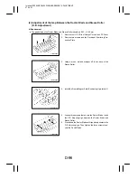
(1) Focus-Positioning of the Scanner and Mirrors Carriage
z
Requirement
D
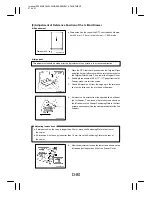
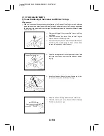
With the Scanner positioned correctly with reference to the Scanner Drive Cable, there should be no
gap between one end of the Scanner/Mirrors Carriage Positioning Jig and the Scanner, and between
the other end of the jig and the Mirrors Carriage. The distance between the Scanner and Mirrors Carriage
should be 83.5 mm.
1134D138AA
1136D046AA
Scanner Positioning Jig
Scanner/Mirrors
Carriage Positioning
Jig
1136D047AA
1136D048AA
83.5mm
1.
Remove the Original Cover, Upper Rear Cover, and Origi-
nal Glass.
2.
Slide the Scanner to a position at which the hole is aligned
with the Scanner Positioning Screw.
3.
Insert a screwdriver into the hole and loosen the Scanner
Positioning Screw. (This allows the Scanner Drive Cable
to move independently of the Scanner.)
4.
Align the rectangular hole in the upper copier frame with
the U-groove in the Scanner. Insert the Scanner Position-
ing Jig.
5.
Install the Scanner/Mirrors Carriage Positioning Jig be-
tween the Scanner and the Mirrors Carriage.
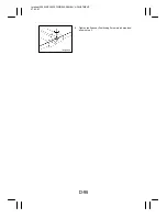
6.
Move the Mirrors Carriage in the direction of the arrow.
7.
Check that both ends of the Scanner/Mirrors Carriage
Positioning Jig have no gap.

