- 8 -
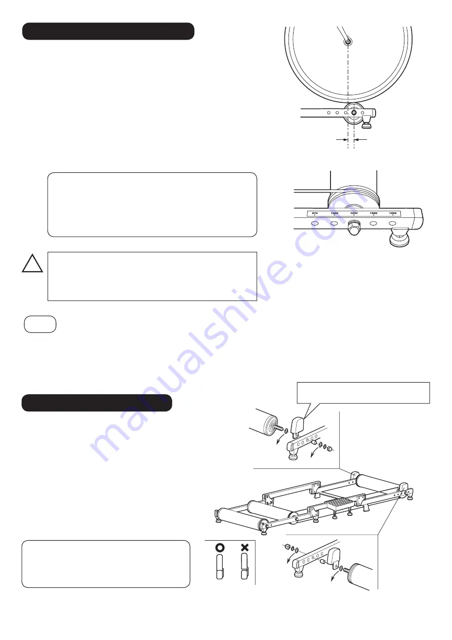
About Front Roller Position
The Front Roller is adjustable in 5 positions in order to fit your bike's wheelbase
size as closely as possible.
The ruler on the right side frame shows the exact number of wheelbase size,
not the calculated number to expect stability. If you already know your bike's
wheelbase size, set the Front Roller at the next hole of your number. Do not
use the smaller number hole for your safety.
To make your ride safe, we recommend you to set the Front Roller at 10 – 15
mm forward to the front wheel axle. (Fig. K)
As your skill increases, this number will get smaller, and the final setting is just
the same number of your wheelbase (just beneath the axle).
!
HINT
The hole pitch on the Front Frame is 30mm. This sometimes makes the front roller position setting difficult to
adjust within 10 – 15mm as suggested, depending on the actual wheelbase size.
For example, if your wheelbase is 980mm, the 970mm position is too short and 1,000mm position is 5 – 10mm
further than the suggestion. It's not recommended.
In this case, you should set the Rear Roller to the front hole on the Rear Frame to move the bike itself 20mm (a
half pitch of the holes) forward. At this moment, you can use the 1,000mm position as 980mm size.
This number corresponds
to the wheelbase when
the Rear Roller is set at
the 27"/700c hole.
How To Install Front Guard
The position just beneath the front wheel axle is only for
expert level riders because the handling becomes so quick
(but natural).
On the rollers, the front wheel will move sideways very
quickly once the roller starts spinning.
The Front Guard is a safety device to push
the front wheel back to center if you lose
balance and nearly drop off from the rollers.
Also the speed can be reduced by the friction
created when the front tire and guard come
in contact with each other.
We recommend the Front Guards for the
beginners.
(Remove)
Remove
Adhere to
the frame
The roller axle length is limited and it may be
too short when installing the Front Guard.
If so you should remove the Flat Washer and
use the guard itself instead of the flat washer.
Face the plastic side toward the tire.
If the front wheel axle is further front than the roller, the
bike will come off the rollers in front very easily.
If positioned too far behind, the bike will feel heavy and
unpredictable.
10 – 15mm (Minimum 0mm. Not negative)
(Fig. K)
(Fig. L)
(Fig. M)
Remove
(Remove)

