background image

Parts List

LM-13

HM-13

VM-9

VM-8

VM-10

VM-11

VM-14

VM-15

VM-12

VM-13

VM-2

VF-7

VM-16

M8-3

M8-4

M8-2

F-8

F-4

F-9

F-1

F-2

F-4

F-7

M8-3

V3-9

V3-1

V3-9

V3-10

V3-11

V3-2

V3-5

V3-6

V3-7

V3-3

HF-4

V3-13

V3-4

V3-12

HF-4

V3-8

F-1: 

Coupling Tube (Right)

F-2: 

Coupling Tube (Left)

F-4: 

Coupling Cover

F-7: 

Hub Handle

F-8: 

Hub Knob Bolt

F-9: 

Coupling Protector

HF-4: 

35mm Rubber Foot Cap

HM-13:  Base Plate

M8-2: 

Main Frame

M8-3: 

38mm Rubber Frame Cap

M8-4: 

32mm Rubber Foot Cap

V3-1: 

U-Frame

V3-2: 

Extension Tube

V3-3: 

Center Frame

V3-4: 

Front Fork Support

V3-5: 

Lock Bracket

V3-6: 

Extension Joint

V3-7: 

Knob Bolt

V3-8: 

32mm End Cap

V3-9: 

22mm Metal Collar

V3-10:  29mm Metal Collar
V3-11:  34mm Metal Collar
V3-12:  32mm Metal Collar
V3-13:  Quick Release Skewer

VF-7: 

Fluid Unit Assy

VM-2:  Inner Housing
VM-8:  Connection Plate

VM-9:  Remote Outer Cover

VM-10:  Spring
VM-11:  Remote Ring

VM-12:  Outer Housing

VM-13:  Magnet
VM-14:  Remote Bracket
VM-15:  Remote Cable
VM-16:  Remote Shifter

Page : 2

Summary of Contents for VFS3R - SCHEMATICS

Page 1: ...he replacement parts within these terms please contact the shop where you purchased this product or the distributor in your country first Only when not available you can contact the following service...

Page 2: ...3 Base Plate M8 2 Main Frame M8 3 38mm Rubber Frame Cap M8 4 32mm Rubber Foot Cap V3 1 U Frame V3 2 Extension Tube V3 3 Center Frame V3 4 Front Fork Support V3 5 Lock Bracket V3 6 Extension Joint V3 7...

Page 3: ...the U frame before installing your bike Check the couplings supporting the rear hub for damage and cracks Accidents may occur from cracked or damaged couplings You should not use the left side knob bo...

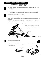
Page 4: ...Remove the lower preassembled part bolt nut and collar on the U Frame Do NOT remove the upper part bolt and nut Put the collar into the hole on the Extension Tube then connect to the U Frame while mak...

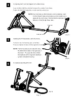
Page 5: ...system in its plastic housing 4 Fig C 5 Connecting the Front Fork Support to the Main Frame Loosen the Knob Bolt then slide the Extension Tune into the Center Frame Tighten the Knob Bolt temporally y...

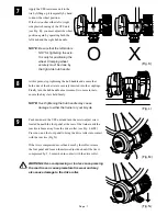
Page 6: ...Fig G Fig H Fig I How To Install Your Bike On Trainer 2 Hold the bike firmly by hand and turn the right side hub handle clockwise until the coupling come into contact with the right side skewer nut 3...

Page 7: ...turn the hub handle a maximum of two more turns to ensure the bicycle is held firmly NOTE Over tightening the hub handle may cause damage to either the trainer or your bicycle Fig L Push downward the...

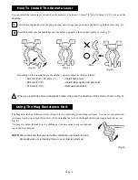
Page 8: ...Lever You can install the remote lever on anywhere the diameter is between 22 2mm 7 8 and 31 8mm 1 1 4 like as on the handlebar Using The Mag Resistance Unit Fig O Fig P 1 2 Fully loosen the knob bol...

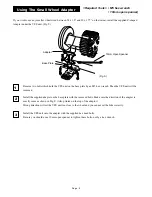
Page 9: ...FS unit will be removed Base Plate Adapter Install the supplied adapter on the base plate with the removed bolts Make sure the direction of the adapter is exactly same as shown in Fig S Also printed o...

Reviews: