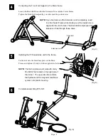
Installing the VFS resistance unit to the frame.
Set the unit onto the black base plate on the Main
Frame, and tighten it firmly with the supplied two bolts.
NOTE:
The fluid resistance unit side with many
fins MUST be located on the right side of
the trainer. The opposite side contains
the flywheel and the magnetic resistance
system in its plastic housing.
4
(Fig. C)
5
Connecting the Front Fork Support to the Main Frame.
Loosen the Knob Bolt then slide the Extension Tune into the Center Frame.
Tighten the Knob Bolt temporally, you will adjust the position later.
(Fig. D)
NOTE:
If you had removed the Extension Joint completely, insert
it to the Center Frame while making sure the inside hole is
aligned to the Joint's hole. The Knob Bolt compressed the
Extension Tube through these holes.
Knob Bolt
Extension Joint
6
Complete assembling VFS-3-R.
(Fig. E)
Page : 5

