background image

Shim

!

The Mag unit side has 7 different levels of load force for replicating actual riding resistance.  You can set your preferred 
resistance level between high (H) and low (L) by adjusting the lever on the thumb shifter type remote lever device (see 
Fig. R).
You may also adjust the load force by shifting up or down among your gears, depend-
ing on the level desired.

NOTE:

 We recommend that you start with a medium to low load force and 

gradually work up, increasing force as your muscles warm up.

How To Install The Remote Lever

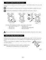
You can install the remote lever on anywhere the diameter is between 22.2mm (7/8”) and 31.8mm (1-1/4”)  like as on the 
handlebar.

Using The Mag Resistance Unit

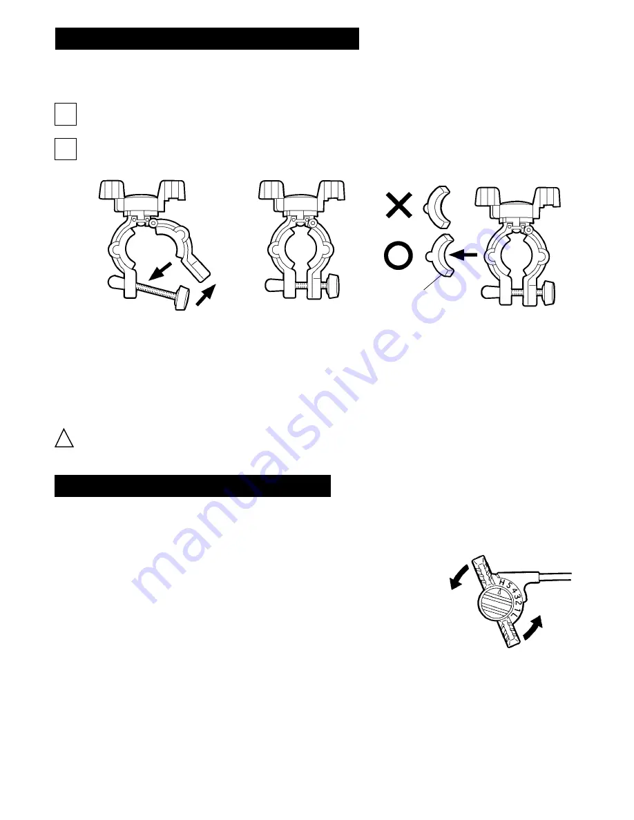
(Fig. O)

(Fig. P)

1

2

Fully loosen the knob bolt on the plastic holder until it stops then push down the bolt to open the holder. (Fig. O)

Place the holder onto the handlebar, shut the holder, and pull up the bolt then tighten it. (see Fig. P)

(Fig. Q)

When you install the shim on the plastic holder, make sure the direction of the shim as shown in Fig. Q.

Depending on the diameter of your handlebar, you must adjust the shim as follows;


• 22.2mm (7/8”) - 25.4mm (1”) : 

...Install both shims


• 28.6mm (1-1/8”) : 


...Install either right or left side shim


• 31.8mm (1-1/4”) : 


...Remove both shims

(Fig. R)

Page : 8

Summary of Contents for VFS3R - SCHEMATICS

Page 1: ...he replacement parts within these terms please contact the shop where you purchased this product or the distributor in your country first Only when not available you can contact the following service...

Page 2: ...3 Base Plate M8 2 Main Frame M8 3 38mm Rubber Frame Cap M8 4 32mm Rubber Foot Cap V3 1 U Frame V3 2 Extension Tube V3 3 Center Frame V3 4 Front Fork Support V3 5 Lock Bracket V3 6 Extension Joint V3 7...

Page 3: ...the U frame before installing your bike Check the couplings supporting the rear hub for damage and cracks Accidents may occur from cracked or damaged couplings You should not use the left side knob bo...

Page 4: ...Remove the lower preassembled part bolt nut and collar on the U Frame Do NOT remove the upper part bolt and nut Put the collar into the hole on the Extension Tube then connect to the U Frame while mak...

Page 5: ...system in its plastic housing 4 Fig C 5 Connecting the Front Fork Support to the Main Frame Loosen the Knob Bolt then slide the Extension Tune into the Center Frame Tighten the Knob Bolt temporally y...

Page 6: ...Fig G Fig H Fig I How To Install Your Bike On Trainer 2 Hold the bike firmly by hand and turn the right side hub handle clockwise until the coupling come into contact with the right side skewer nut 3...

Page 7: ...turn the hub handle a maximum of two more turns to ensure the bicycle is held firmly NOTE Over tightening the hub handle may cause damage to either the trainer or your bicycle Fig L Push downward the...

Page 8: ...Lever You can install the remote lever on anywhere the diameter is between 22 2mm 7 8 and 31 8mm 1 1 4 like as on the handlebar Using The Mag Resistance Unit Fig O Fig P 1 2 Fully loosen the knob bol...

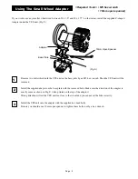
Page 9: ...FS unit will be removed Base Plate Adapter Install the supplied adapter on the base plate with the removed bolts Make sure the direction of the adapter is exactly same as shown in Fig S Also printed o...

Reviews: