32
down on them while turning them towards zero. They
will automatically lock into place when you have
reached the zero position.
Note:
When unlocking the adjustment caps, the
seals within the turrets may cause a slight vacuum
and pull them back towards the turret if they are left
at zero. As soon as the caps have been turned, this
effect will not occur.
The click mechanism within the reticle adjustment
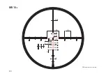
turrets is engineered to perform in 0.1 mrad steps.
One click of 0.1 milliradiants (mrad) is equivalent to
1 cm / 100 m or approx. 1/3 MOA. The riflescopes are
available with “CCW” (counterclockwise) turrets. The
direction of rotation indicates the direction in which the
caps must be turned to change the point of impact “up”
or “right”. The turrets are equipped with a Zero Stop,
limiting the rotation of the adjustment caps. The zero
stop is permanent and does not need to be adjusted. It
is designed to stop the rotation of the elevation a few
clicks below the zero position and to l imit its rotation to
one complete turn. To zero your scope to your weapon,
adjust the elevation and windage caps until point of
impact matches point of aim.
When impacts are “low”, adjust the elevation cap to-
wards “high”, when impacts are “left”, adjust the wind-
age cap towards “right” and vice versa. The caps can be
loosened using a 2 mm allen key and tightened again after
turning the caps to the zero position. When the caps have
been loosened, the clicks are not audible, indicating that
the caps have been successfully loosened from the turret.
Note:
If while zeroing your scope you have reached
the Zero Stop (for example if the shots are repeatedly
too high and the elevation cap cannot be turned
“down” any further), loosen the allen screws on the
cap and turn it several mrads in the opposite
direction. Push the cap down and tighten the screws
again. You will now have more adjusting range to
achieve the desired point of impact. The same proce-
dure can be carried out with the windage turret.
To set the caps to zero after zeroing your scope, slightly
loosen the allen screws with a 2 mm allen key. About half
a turn should be enough. Turn the caps to the zero
position, push them down to the “locked” position and
tighten the screws again. It is advisable to use the
shorter end of the key to avoid too much torque when
tightening the screws.
Summary of Contents for ZP 8
Page 1: ...Bedienungsanleitung Instructions MINOX ZP8 Zielfernrohr Riflescope...
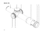
Page 4: ...1 4 5 6 7 8 2 3 4 MINOX ZP8...
Page 14: ...0 25 10 0 15 1 1 2 0 15 2 1 5 14 MR10 Einheit der Bema ung Milliradiant mrad...
Page 15: ...0 25 100 10 0 15 1 1 2 0 15 15 MR10 Einheit der Bema ung Milliradiant mrad...
Page 16: ...10 0 15 1 0 15 1 16 A8 D Einheit der Bema ung Milliradiant mrad...
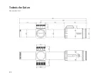
Page 22: ...Technische Daten Abmessungen mm 22...
Page 26: ...1 4 5 6 7 8 2 3 26 MINOX ZP8...
Page 34: ...0 25 10 0 15 1 1 2 0 15 2 1 5 34 MR10 All dimensions are in mrad...
Page 35: ...0 25 100 10 0 15 1 1 2 0 15 35 MR10 All dimensions are in mrad...
Page 36: ...10 0 15 1 0 15 1 36 A8 D All dimensions are in mrad...
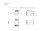
Page 41: ...Technical data Dimensions mm 41...
Page 43: ...43 Notes...


