background image


REAR SQUEEGEE ADJUSTMENT 


1.  Ensure that the scrubber is on a relatively flat surface. Turn on the key switch and lower the 

squeegee to the floor using the squeegee lift lever. This turns the vacuum motor on. 

 
2.  Move the scrubber one or two feet forward slowly while someone behind the machine checks 

the rear squeegee blade (item 

A

) for uniform deflection to the floor. 

 
3.  If uneven deflection or lay is evident, minor adjustments may be necessary to avoid streaking 

and uneven wear on the blade. 

 
4.  To correct this, loosen the wing jam nut (item 

B

) in order to adjust the caster height. If the 

squeegee blade is deflecting too much, the casters (item 

D

) need to be lowered to control the 

down pressure. Lower the caster by turning the exposed threaded stem (item 

C

) on the 

caster clockwise. Make the adjustment a few turns at a time. 

Repeat step 2

 
5.  If the blades are not deflecting enough, raise the caster by turning the stem counter-

clockwise to adjust the caster height to allow more down pressure on the squeegee. 

Repeat 

step 2.


6.  Make sure there is even deflection on the entire length of the rear blade. Adjust the casters 

and retighten the wing jam nuts to lock the caster setting in place.  

 
7.  Pitch adjustment is necessary if the outer ends on the squeegee blade do not contact the 

floor and there is too much deflection in the middle area or if the outer ends are over 
deflected and there is no contact in the middle. 

 
8.  To adjust the pitch, Repeat step 2. 
 
9.  Loosen the two wing jam nuts (item 

E

) that lock the pitch angle. Turning the knob (item 

F

clockwise or counter-clockwise controls the forward and backward pitch of the squeegee. 
Having the rear blades deflected uniformly along its entire length is the desired set-up. 

 
10.  Repeat step 2 until desired set-up is achieved. 
 
11.  In certain applications where a non-slotted front wiper blade (item 

G

) is needed, detach the 

      rear squeegee assembly by loosening the two wing bolts (item 

H

). Unlock the toggle clamp 

      (item 

I

) on the front squeegee to release the front long strap (item

 J

) and slide the front short  

      strap (item 

K

). Flip the blade over to the non-slotted side. Reattach the straps and lock the  

      clamp back in place. 
 
12.  You can also easily replace the rear blade by unlatching the latch (item 

N

) and removing the 

       two rear straps (items 

L

 & 

M

) by sliding them off the assembly. You can then flip the blade 

       over in order to use a new edge for better wiping action. 

Summary of Contents for P260BDCE

Page 1: ...OPERATION SERVICE PARTS CARE ES260 Floor Scrubber Traction Driven Brush Driven Model P260TDQP P260TDCE P260TDQPIW P260BDQP P260BDCE...

Page 2: ......

Page 3: ...BRUSH DRIVE 12 LINKAGE ASSEMBLY BRUSH DRIVE 13 LINKAGE ASSEMBLY BOM BRUSH DRIVE 14 CONTROL PANELS BRUSH DRIVE 15 CONTROL PANELS BOM BRUSH DRIVE 16 SOLUTION RECOVERY TANK TRACTION DRIVE 17 SOLUTION REC...

Page 4: ...Store or park this machine on a level surface only with the key switch in the off position To prevent unauthorized use machine should be stored with the key removed This machine is designed for level...

Page 5: ...batteries BATTERY INSTALLATION 1 Disconnect tank drain hose from rear of machine 2 Raise the tank assembly by raising rear cover and tilting tank Figure 1 3 Install batteries as shown in Figure 2 CHAR...

Page 6: ...3 CONTROL PANEL IDENTIFICATION...

Page 7: ...ly with lever 2 This will turn on the vacuum motor The vacuum will remain on until the squeegee lever 2 is raised After this the motor will continue to run for an additional 10 seconds to clear the re...

Page 8: ...pplications Each blade configuration has two usable edges The rear blade however has four usable edges The squeegee is pre adjusted at the factory Adjustments may be required to get optimum performanc...

Page 9: ...Adjust the casters and retighten the wing jam nuts to lock the caster setting in place 7 Pitch adjustment is necessary if the outer ends on the squeegee blade do not contact the floor and there is to...

Page 10: ...EXPLODED VIEWS MAIN ASSEMBLY 7...

Page 11: ...2 CLAMP HOSE 102120 MURRAY 19 260212 1 SCREEN FILTER 20 260241 2 PIN HITCH 7 16 X 3 21 260294 1 GASKET 260 22 260299 1 SHUT OFF PLATE ASY 23 260301 1 DEFLECTOR FLAP 24 260336 1 SKIRT RETAINER FRONT 2...

Page 12: ...SOLUTION AND RECOVERY TANK BRUSH DRIVE 9...

Page 13: ...INGE 24 450040 2 ELBOW PLT 3 8MPTX3 8BARB 25 450055 1 HOSE NYLO 3 8ID X 9 26 450076 12 CLAMP CRIMP 185R SS 27 450081 1 WSR 1 908 X 2 41 X 03 SS 28 710353 2 SCR MC 10 32 X 37 ZINC 29 710985 2 SC 3 8 16...

Page 14: ...MAINFRAME ASSEMBLY BRUSH DRIVE 11...

Page 15: ...4 711250 2 BLT HH 3 8 16 X 1 25 STL ZINC 25 711374 2 NUT NYLOC 5 16 18 26 711375 2 NUT NYLOC 3 8 16 1 2NUT 27 711380 2 NUT NYLOC 3 8 16 28 711439 3 NUT FLANGED WIZZ 3 8 16 29 711507 2 WSR FLT 37 X 1 1...

Page 16: ...LINKAGE ASSEMBLY BRUSH DRIVE 13...

Page 17: ...1 CABLE BRACKET WELDMENT L H 60 711717 2 RET RING E EXT 37 18 260124 1 CABLE BRACKET WELDMENT R H 61 712129 2 SCR TR 1 4 20X 1 00 HWH 19 260137 1 SPRING COMP 960 X 2 00 ZINC 62 712301 2 WSR FLT 37 X...

Page 18: ...CONTROL PANELS BRUSH DRIVE 15...

Page 19: ...R GLASTIC 15 260325 1 HANDLE BRACKET 47 740247 1 CIRCUIT BREAKER 30AMP PUSH BUTTON 16 260337 1 CABLE SQUEEGEE 48 740216 1 GUAGE BATTERY COND 17 320248 2 CLEVIS SLOTTED 49 740241 1 CONTACT 24V 50AMP 18...

Page 20: ...SOLUTION AND RECOVERY TANK TRACTION DRIVE 17...

Page 21: ...0040 2 ELBOW PLT 3 8MPTX3 8BARB 27 450055 1 HOSE NYLO 3 8ID X 9 28 452037 15 CLAMP CRIMP 170R SS 29 450081 1 WSR 1 908 X 2 41 X 03 SS 30 710353 2 SCR MC 10 32 X 37 ZINC 31 710985 2 SC 3 8 16 X 62 32 7...

Page 22: ...MAINFRAME ASSEMBLY TRACTION DRIVE 19...

Page 23: ...HEX 5 16 18 SS 13 260256 1 BASE 260TD CHAR GREY 39 713042 4 BLT HH 3 8 16 X 1 00 5 14 260660 1 SQUEEGEE LIFT ASSY ES260320 40 713045 1 BLT HH 3 8 16 X 1 75 5 15 260360 1 MAINFRAME MMAN 260 TD 41 7130...

Page 24: ...LINKAGE ASSEMBLY TRACTION DRIVE 21...

Page 25: ...RING E EXT 50 15 260150 1 BATTERY LINER 54 711808 2 PIN HAIRPIN COTTER 13 16 260159 1 HOSE VAC 1 5 X 78 WIRELOC 55 712301 6 WSR FLT 37 X 87 X 06 WIDE 17 210466 1 CABLE CONDUIT 56 712310 25 WSR FLT 52...

Page 26: ...CONTROL PANELS TRACTION DRIVE 23...

Page 27: ...BREAKER 60AMP PUSH BUTTON 19 320248 2 CLEVIS SLOTTED 59 740804 1 POTENTIOMETER ASSY 20 281579 1 SCV SQUEEGEE BLADE ASSY 32 60 740944 1 1 SPD CONT 24V 1203A225 21 430051 2 SPRING RETURN 313 X 438 X 2...

Page 28: ...SQUEEGEE LIFT MECHANISM ASSEMBLY P N 260660 25...

Page 29: ...BRACKET ASSEMBLY 8 430051 2 SPRING RETURN 313 X 438 X 2 93 SS 9 710592 2 SCR MC TH 1 4 20 X 3 00 SS 10 711425 4 NUT FLANGED WIZZ 1 4 20 STL ZP 11 711517 2 WSR FLT 77 X 1 37 X 03 12 711524 1 WSR WAVE 5...

Page 30: ...SQUEEGEE ADJUSTMENT MECHANISM ASSEMBLY P N 241730 1 27...

Page 31: ...SQUEEGEE BLADE ASSEMBLYP N 281579 28...

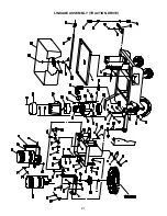
Page 32: ...WIRING DIAGRAM TRACTION DRIVE 29...

Page 33: ...WIRING DIAGRAM TRACTION DRIVE cont d 30...

Page 34: ...WIRING DIAGRAM TRACTION DRIVE CE 31...

Page 35: ...WIRING DIAGRAM TRACTION DRIVE CE cont d 32...

Page 36: ...WIRING DIAGRAM BRUSH DRIVE 33...

Page 37: ...WIRING DIAGRAM BRUSH DRIVE cont d 34...

Page 38: ...WIRING DIARGRAM BRUSH DRIVE CE 35...

Page 39: ...WIRING DIARGRAM BRUSH DRIVE CE cont d 36...

Page 40: ...e U S A and Canada should contact their local distributor for export warranty policies Minuteman is not responsible for costs or repairs performed by persons other than those specifically authorized b...

Reviews: