background image

4

Table of Content

Introduction  . . . . . . . . . . . . . 2

Preface. . . . . . . . . . . . . . . . . . 2
Proper use . . . . . . . . . . . . . . . 2
Notes of warranty . . . . . . . . . . 3
Acceptance of the machine . . 3

1

Safety information . . . . . . . . 5

1.1

Safety and Warning Symbols. 5

1.2

General Provisions. . . . . . . . . 6

1.3

Provisions for Operation. . . . . 6

1.4

Maintenance instructions . . . . 7

1.5

Specific Hazards  . . . . . . . . . . 7

1.6

Information for Protection of En-
vironment . . . . . . . . . . . . . . . . 8

1.7

Labels at the Machine  . . . . . . 9

2

First Operation . . . . . . . . . . 10

2.1

Instruction. . . . . . . . . . . . . . . 10

2.2

Initial charging procedure. . . 10

2.3

Before Putting into Operation 10

2.4

Start Machine . . . . . . . . . . . . 10

2.5

Operation . . . . . . . . . . . . . . . 11

2.6

Stop Machine . . . . . . . . . . . . 11

2.7

After Work  . . . . . . . . . . . . . . 11

2.8

Transporting the machine  . . 11

2.9

Tie-down points . . . . . . . . . . 11

3

Operation  . . . . . . . . . . . . . . 12

3.1

Method of Operation  . . . . . . 12

3.1.1 Brush Head  . . . . . . . . . . . . . 12
3.1.2 Solution Tank . . . . . . . . . . . . 12
3.1.3 Squeegee. . . . . . . . . . . . . . . 13
3.1.4 Recovery Tank . . . . . . . . . . . 13
3.1.5 Travel Drive . . . . . . . . . . . . . 13
3.1.6 Batteries and Charger  . . . . . 13
3.1.7 Options. . . . . . . . . . . . . . . . . 13
3.2

Operating and Indicating Ele-
ments . . . . . . . . . . . . . . . . . . 14

3.2.1 Operating Panel . . . . . . . . . . 14
3.2.2 At the machine . . . . . . . . . . . 17

4

Technical Data . . . . . . . . . . 20

5

Maintenance and Care . . . . 22

5.1

Minuteman System Mainte-
nance . . . . . . . . . . . . . . . . . . 22

5.2

Maintenance Document . . . . 23

5.3

Maintenance Schedule. . . . . 24

5.4

Battery Systems . . . . . . . . . . 28

5.4.1 Charge Batteries  . . . . . . . . . 29
5.4.2 Low Discharge Signal sender 

(LDS) . . . . . . . . . . . . . . . . . . 29

5.4.3 Maintenance of Drive Batteries  

29

5.4.4 Remove Batteries. . . . . . . . . 29
5.4.5 Install Batteries. . . . . . . . . . . 29

5.4.6 Disposal of Batteries  . . . . . .  29
5.5

Solution Tank . . . . . . . . . . . .  30

5.5.1 Fill Solution Tank . . . . . . . . .  31
5.5.2 Empty Solution Tank  . . . . . .  31
5.5.3 Clean Solution Filter. . . . . . .  31
5.6

Soiled Water Tank . . . . . . . .  32

5.6.1 Empty Soiled Water Tank  . .  33
5.6.2 Clean Soiled Water Tank . . .  33
5.6.3 Clean Suction Filter . . . . . . .  33
5.7

Plate brush head  . . . . . . . . .  34

5.7.1 Clean Brushes . . . . . . . . . . .  34
5.7.2 Change Brushes  . . . . . . . . .  34
5.7.3 Change Deflector Roller. . . .  34
5.7.4 Change Sealing Strip . . . . . .  34
5.8

Squeegee. . . . . . . . . . . . . . .  35

5.8.1 Cleaning the Squeegee . . . .  35
5.8.2 Changing the Sealing Strips.  35
5.8.3 Adjusting the Sealing Strips .  36

EC-Declaration of Conformity

. . . . . . . . . . . . . . . . . . . . . . .  39

Summary of Contents for 7311.24

Page 1: ...Instruction Manual E33XL 7311 24 ...

Page 2: ...ase be advised explicitly that we cannot accept any legal issues out of the contents of this manual If repair work has to be performed make sure that only genuine spare parts are used only genuine spare parts may guarantee a dependable machine We reserve the right for technical im provement Valid as of March 2008 Minuteman International Inc 111 South Rohlwing Road ADDISON II 60101 4244 U S A Prope...

Page 3: ...orized modification of the machine Moreover any claim for war ranty cannot be accepted if damages of the machine are caused by fitting parts or accessories without Minuteman s pri or and explicit consent or by non com pliance with the maintenance instructions Acceptance of the machine Upon arrival check machine for possi ble damages in transit Follow un packing instructions on shipping pallet Each...

Page 4: ...7 Options 13 3 2 Operating and Indicating Ele ments 14 3 2 1 Operating Panel 14 3 2 2 At the machine 17 4 Technical Data 20 5 Maintenance and Care 22 5 1 Minuteman System Mainte nance 22 5 2 Maintenance Document 23 5 3 Maintenance Schedule 24 5 4 Battery Systems 28 5 4 1 Charge Batteries 29 5 4 2 Low Discharge Signal sender LDS 29 5 4 3 Maintenance of Drive Batteries 29 5 4 4 Remove Batteries 29 5...

Page 5: ... wing warning symbols Symbol Hazardous for Description Safety Provisions persons and goods Safety Provisions in dangerous situation caused by misuse inaccurate adherence of instructions or pres cribed work routine CAUTION the machine important information on handling the machine in order to maintain operability Ecological hazard the environment due to use of substances representing an inherent dan...

Page 6: ...ully charge the battery with an initial charging procedure and comply with the operating instructions of the charger as well as with those of the battery manufacturer Minuteman cannot be held liable for damages resulting from an insufficient initial charge Before taking into operation check the machine for operational safety Immediately remedy malfunctions It is indispensable for the operator to g...

Page 7: ...e removed When performing work at the electri cal system be sure to disconnect the battery plug Make sure to protect the recovery tank against accidental closing or til ting down before working in the area of a lifted tank lid Do not clean the electrical parts by means of high pressure cleaning equipment The use of aggressive detergents is prohibited Let the machine dry after cleaning The machine ...

Page 8: ...danger to health and environment specific knowledge is required Observe the legal directives and lo cal regulations for disposal of deter gents Used batteries labelled as recyclable contain reusable economic goods According to the crossed dustbin la bel these batteries must not be ad ded to the normal waste ...

Page 9: ...eplace missing or illegible labels immediately Minuteman nameplate Fig 1 1 Machine identification number Fig 1 2 Recovery tank drain hose Fig 1 3 A Read and observe the instruction manual Fig 1 2 B Maximum inclination of 10 Fig 1 2 C Do not clean the machine by means of high pressure cleaning equipment Fig 1 2 Fig 1 A B C 10 1 2 3 ...

Page 10: ... of leakage Hoses lines and tanks must be free from any lea kage or damage 2 Install brushes and squeegee see maintenance chapter 3 Install batteries and connect battery plug see maintenance chapter 4 Check battery charge and proceed to re charging of batteries if required Generally proceed to initial charging before first operation of the machine 5 Empty recovery tank and clean it if required see...

Page 11: ...e machine against unintentional mo vements or against being inadvertently started 2 7 After Work 1 Move the machine to a suitable site for maintenance 2 Stop machine lift squeegee and brush head and remove the key 3 Empty and clean recovery tank Observe the legal directives and local regulations for dispo sal of detergents 4 Check solution filter 5 Check seals and suction hose 6 Check operating fl...

Page 12: ... brushes rotate and solution supply switches on auto matically When the machines stopped brushes and solution supply switch off automatically 3 1 2 Solution Tank Fill the solution tank Fig 3 2 after re moving the cover The solution tank holds 29 8 gallons and the filling level can be checked visually through trans parent hose Regulation of solution amount is available via adjustment handle Fig 3 2...

Page 13: ...is taken from squee gee to the recovery tank Fig 3 4 by suction turbine and suction hose 3 1 5 Travel Drive The machine features a continuous tra vel drive Fig 3 6 The electronic travel drive control realises modification of tra vel speed direction as well as dynamic braking 3 1 6 Batteries and Charger The machine is equipped with 235 Ah batteries Fig 3 5 an automatic char ger unit Fig 3 7 and a l...

Page 14: ...e 7 Hourmeter 8 Symbol Service indicator 9 Symbol Park brake 10 Symbol Silence Kit optional 11 Symbol solution dosage 12 Tip switch Silence Kit optional 13 Tip switch solution dosage 14 Tip switch solution supply On Off 15 Symbol vacuum scrubbing tool optional 16 Drive direction control 16a with speed control knob 16b and bail handle 16c Fig 4 1 7 9 8 4 3 12 6 13 10 14 5 2 11 15 16a 16c 16b ...

Page 15: ...n is output on the panel to show the cur rent battery charge condition during operation Additional Information see chapter maintenance Symbol brush drive Fig 4 5 This symbol appears when brush drive is switched on Symbol suction turbine drive Fig 4 6 This symbol appears when suction tur bine drive is switched on Hourmeter Fig 4 7 Upon switching on the hourmeter briefly displays the software versio...

Page 16: ...n supply ON OFF tip switch Fig 4 14 This tip switch is used to switch solution supply ON or OFF Scrubbing tool symbol optional Fig 4 15 This symbol appears when scrubbing tool switch A is switched on Hand cleaning tool optional Hand cleaning tool with spray function for a machine with scrubbing tool con nection for thorough cleaning on areas which are difficult to reach Drive direction control wit...

Page 17: ...rush head 2 Opening of solution tank 3 Hand lever for squeegee lift out 4 Solution filter 5 Recovery drain hose 6 Solution level indication 7 Brush ejector 8 Power connection charger unit 9 Pedal plate brush head pressure Fig 5 2 3 5 7 8 6 4 1 9 ...

Page 18: ...om tank to brush head it is cleaned by the filter element Recovery tank drain hose Fig 5 5 This hose allows draining the collected soiled water from the tank Solution tank drain hose Fig 5 6 This hose allows draining the solution tank Brush ejector Fig 5 7 The brush ejector makes brush removal fast and easy Power connection charger unit Fig 5 8 The power connection supplies the charger unit with p...

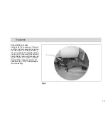
Page 19: ...rough nar row clearances This can be done by foot or by hand by swinging the squee gee to the left in the area of the deflector bail deflector roller until the locking pin Fig 6 1 catches In order to release locking of the squeegee actuate the hand lever Fig 5 3 of the squeegee lift out lowering Fig 6 1 ...

Page 20: ... 33 Squeegee width in 44 Surface performance theoretical ft h 36600 Service voltage V 24 Nominal power drive motor W 430 Nominal power suction motor W 520 Nominal power brush motor W 2x935 Number of brushes Qty 2 Diameter of brushes in 17 Work ride mph 3 0 Solution tank gallon 30 Recovery tank gallon 30 Weight without batteries and solution lbs 496 Weight with solution and batteries lbs 1155 ...

Page 21: ...ts to dB A 82 80 79 The sound pressure level measured at the ear of the driver under normal conditions of use LpA according to DIN EN 60335 2 72 amounts to dB A 67 65 63 Measurement inaccuracy KpA dB A 1 6 1 6 1 6 Vibration The frequency weighted acceleration measured accor ding to DIN EN ISO 5349 which have an effect upon the upper limbs hand arm system amounts under normal working conditions m s...

Page 22: ...vice life and opera bility of the machine The Minuteman System Maintenance is structured in separate modules and de termines specific technical works to be executed as well as the intervals for such maintenance works For any spe cific maintenance type the replacement parts are determined and listed in spare part kits System Maintenance K To be performed by the customer in ac cordance to the mainte...

Page 23: ..._______ operating hours System Maintenance I 625 operating hours Workshop stamp carried out on at _________________ operating hours System Maintenance II 750 operating hours Workshop stamp carried out on at _________________ operating hours System Maintenance I 875 operating hours Workshop stamp carried out on at _________________ operating hours System Maintenance S 1000 operating hours Workshop ...

Page 24: ...ead and clean if required o Check squeegee and clean if required o Clean tank lid seal of the recovery tank o Empty recovery tank Clean recovery tank and suction filter o Check brushes pads and replace if required o Clean suction hose of recovery tank o Check squeegee sealing strips and turn around or replace if required o Clean drain hose of solution tank o Check solution supply to brushes and cl...

Page 25: ...25 hours of operation Check battery charger o Check tank lid seal of the recovery tank and replace if required o Check drain hose of the recovery tank and replace if required o Grease joints at the brush lift out o Check wheel fixing screws and tighten 24 lb ft if required o Check condition of tires o Grease joints at the squeegee holder o Test drive and function test o ...

Page 26: ...ording to System Maintenance I o Inspect steering rollers for tread damages and bearing slackness and replace if required o Check drain hose of the recovery tank and replace if required o Check deflector roller of the brush head and replace if required o Check suction hose for tight fitting and damages and replace if required o Check supporting wheel of the squeegee and replace if required o Test ...

Page 27: ...every 500 hours of operation Perform maintenance works according to System Maintenance II o Clean travel drive motor from carbon dust and check carbon brushes for smooth operation and wearing and replace carbon brushes if required o Clean brush motors from carbon dust and check carbon brushes for smooth opera tion and wearing and replace carbon brushes if required o Test drive and function test o ...

Page 28: ...rt 9 Wiring diagram Handling and changes of the batteries may take place only by maintenance staff During operation the LDS indi cator displays the battery char ge status When the batteries are empty the battery icon flashes and an acoustic warning signal is issued The machine functions are restric ted Drive to a charging station immediately Fig 7 4 3 1 2 6 5 8 7 9 ...

Page 29: ... has been integrated into the electronics If other batteries are used re adjustment of the low discharge signal sender is required Only Minuteman contract workshops are authorized to adjust the low discharge signal sender 5 4 3 Maintenance of Drive Batte ries Refer to operating instructions 88 60 2556 for information on care of drive batteries 5 4 4 Remove Batteries 1 Park machine on level ground ...

Page 30: ...30 Maintenance and Care 5 5 Solution Tank 1 Solution tank 2 Marker 3 Fill level hose 4 Solution filter 5 Tank lid Fig 8 5 3 1 2 4 ...

Page 31: ...ng instructions for information on operation of the do sage unit The maximum admissible service pres sure of the floater unit is 6bar 5 5 2 Empty Solution Tank Park vehicle such that the fill level hose Fig 8 3 is located above the drain aperture in the floor Take fill level hose from holder and remove lid 5 5 3 Clean Solution Filter Check solution filter Fig 8 4 at weekly intervals and clean or r...

Page 32: ...32 Maintenance and Care 5 6 Soiled Water Tank 1 Soiled Water Tank 2 Drain hose 3 Suction filter 4 Tank lid Fig 9 3 4 2 1 ...

Page 33: ...nts 4 Take drain hose Fig 9 2 from hol der and empty soiled water tank completely 5 6 2 Clean Soiled Water Tank Clean soiled water tank Fig 9 1 at dai ly intervals or as required 1 Empty soiled water tank see para graph 5 6 1 2 Open tank lid Fig 9 4 of the soiled water tank 3 Take drain hose Fig 9 2 from hol der and empty soiled water tank completely 4 Remove remaining dirt by rinsing with clear w...

Page 34: ...d for wearing at weekly intervals Replace brushes if bristles are worn down to a length of 1 5 cm 1 Press brush ejectors Fig 10 3 down to remove old brushes 2 Push new brush under brush head and use both hands to press it into seating 5 7 3 Change Deflector Roller Check deflector roller Fig 10 4 at weekly intervals or replace as required 5 7 4 Change Sealing Strip Check sealing strip Fig 10 5 at w...

Page 35: ...the two star shaped knobs Fig 11 2 and remove the squeegee 5 8 2 Changing the Sealing Strips Check the inner and outer sealing strips on the squeegee Fig 11 1 weekly for signs of wear The sealing strips can be used fourfold by turning them 1 Lift the squeegee out 2 Pull off the suction hose loosen the two star shaped knobs and remove the squeegee 3 Unlock the fastening device Fig 11 5 and remove t...

Page 36: ...of the sealing strips still have contact with the floor Figure A Turn the eccentric wheel in the front top position The clearance between sealing strip and floor is re duced in the centre Figure B Turn the eccentric wheel in the behind top position The clearan ce between sealing strip and floor is increased in the centre 3 Switch the machine on and check the suction pattern When the machi ne is in...

Page 37: ...der In the case of very smooth floors e g fi nished floors PVC linoleum etc Number of washers 2 This corre sponds to a clearance of approx 2 mm In the case of very uneven floors e g poorly laid tiles water does not run off Number of washers 4 This corre sponds to a clearance of approx 4 mm The Squeegee 110 cm is equipped with two additional rollers which are adjusted at the factory to a distance o...

Page 38: ...38 Maintenance and Care ...

Page 39: ...quirement of the Directive 98 37 EC and to the requirements of the other relevant Directives 89 336 EEC For the relevant implementation of the safety and health requirements mentio ned in the Directives the following stan dard s and or technical specification s has have been respected DIN EN 60335 2 72 DIN EN 61000 6 2 DIN EN 61000 6 3 Bad Oldesloe 20 03 2008 Bernd Heilmann Managing director EC De...

Page 40: ...eplacement filters and or prefilters not manufactured by Minuteman or its designated licensees will void all warranties expressed or implied A potential health hazard exists without original equipment replacement All warranted items become the sole property of Minuteman or its original manufacturer whichever the case may be Minuteman disclaims any implied warranty including the warranty of merchan...

Page 41: ...two years labor ninety days travel Not to exceed two hours Exceptions Port A Scrub one year parts six months labor MPV 13 one year parts MPV 14 and 18 two years parts one year labor Rapid Air blower one year parts one year labor Pneumatic Vacuums three years parts one year labor EX 12 and EX 12H one year parts one year labor Battery Operated Group Three years parts two years labor ninety days trav...

Page 42: ...Excellence Meets Clean Minuteman International Inc 111 Rohlwing Road ADDISON II 60101 4244 U S A Phone 001 630 6276900 Fax 001 630 6271130 88 10 2813 ...

Reviews: