background image

14.  Hydrometer Testing The Batteries 

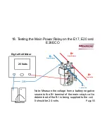
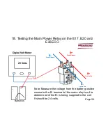
To do an accurate test, the battery water level must be high enough to
extract enough electrolyte to fill hydrometer so that the float floats.
Water should be added prior to charging in order for let the electrolyte
to mix.

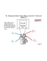
The greater the variation  between cells readings, the greater the loss 
of run time.  For example, if the readings are 1.265, 1.265 and 1.225 in 
one 6 volt battery.  The low cell would be considered weak and greatly 
reduce the performance of the battery or shorter run time.  This 
battery would have a point 40 variation.   Batteries that have weakened 
cells in most cases it can still be used as long they continue provide 
adequate run time. A battery with a point 40 variation or more should 
be determined defective. 

Hydrometer Testing

Page 48 

Summary of Contents for E17BD

Page 1: ...All E17BD E17TD E20S E20BD E20TD E20C H20BD H20TD E26ECOS and E26ECO Automatic Scrubbers Service Manual For Training Troubleshooting Adjustments Revised 02 10 2019 ...

Page 2: ...4 Maintenance S after every 500 hours of operation Page 13 4 Batteries and Wiring Page 14 5 Recovery Float and Gasket Page 15 6 Lubrication Page 16 7 Charge Indicator Version 1 Page 17 8 On Board Chargers 957760 and 957761 Ver 1 2 Page 18 8 1 Programming the 957745 Charger Page 19 8 2 Charger Settings 957745 Page 20 8 3 Battery Charger Trouble Shooting Page 21 8 4 Battery Charger Error Codes 95774...

Page 3: ...ge 38 11 Squeegee Adjustment Curved Page 39 11 1 Squeegee Adjustment Page 40 11 2 Squeegee Caster Adjustment Page 41 11 3 Squeegee Caster Adjustment Page 42 11 4 Squeegee Caster Adjustment Page 43 12 Maintaining Deep Cycle Wet Batteries Page 44 13 Load Testing The Batteries Page 46 14 Hydrometer Testing Page 47 15 Transporting the Machine Page 50 16 Key Switch Page 51 17 Solution Filter new and ol...

Page 4: ...t Page 59 19 1 Trouble Shooting The Traction Drive Switch Page 60 19 2 Trouble Shooting Vacuum Motor Circuit Page 61 19 3 Trouble Shooting Vacuum Relay Page 62 19 4 Testing the Drive System Potentiometer Page 63 20 Notes Page 64 Contents ...

Page 5: ...ove metal jewelry Do not lay tools or metal objects on top of the batteries 4 Do not clean machine with a pressure washer 5 Only authorized personnel should perform repairs and maintenance 6 Use only Minuteman genuine replacement parts 8 Do not use machine around flammable substances 9 The batteries should be charged only in well ventilated areas 10 Always disconnect the battery pack from the mach...

Page 6: ...2 Technical Specifications E17BD E20 Page 6 ...

Page 7: ...2 1 Dimensions E17BD E20 BD With a Straight Squeegee Page 7 ...

Page 8: ...2 2 Dimensions E17 E20 With Curved Squeegee Page 8 ...

Page 9: ...as specified in the operating instructions The operator must be professionally instructed after delivery of the machine by selling dealer Minuteman System Maintenance I after every 125 hours of operation To be preformed an authorized Minuteman Service Center in accordance with the machine specific system maintenance Minuteman System Maintenance II after every 250 hours of operation To be preformed...

Page 10: ...n the recovery tank O Empty and flush the recovery tank with clean water O Clean the filter float inside the recovery tank O Check the water levels of all the batteries Add distilled water if needed Do not over fill O Check the pads and brushes for wear Replace if needed O Check the squeegee hose for clogs damage and wear Replace if needed O Check the squeegee rubbers for cuts and wear Flip the bl...

Page 11: ...3 2 Minuteman System Maintenance I Page 11 ...

Page 12: ...3 3 Minuteman System Maintenance II Page 12 ...

Page 13: ...3 4 Minuteman System Maintenance S Page 13 ...

Page 14: ...teries connected in series Connect the batteries according the battery wiring diagram to the right The recommended batteries are two 12 volt 115 Ah deep cycle battery part number 956712 for the Wet Lead Acid type or 12 volt 100Ah AGM Maintenance Free is part number 956100 Do not use Automotive or Marine type batteries When changing the type of battery going to Gel from Wet Lead Acid or visa versa ...

Page 15: ...ach use and cleaned if needed Remove the three screws and the cover to access screen float for more extensive cleaning Failure to do so will reduce the vacuum performance of the machine Using the machine without it in place or picking up dry material will damage the vacuum motor 3 screws cover screen float Page 15 ...

Page 16: ...rous amount of grease into the fittings on the machine until grease seeps out around the bearings Wipe excessive grease off with a towel The grease points are listed below 1 Rear squeegee caster wheel axle 2 2 Rear squeegee caster swivel 2 Apply lubricant to 1 The rear squeegee pivot points 2 The scrub deck linkages 6 Lubrication Page 16 ...

Page 17: ...es the batteries need a full charge The yellow light indicates the batteries have received 80 of their charge The green light indicates the batteries are fully charged The red light is flashing indicates the charger has detected a fault in the batteries See Section 8 6 Applies to the 957760 and 957761 chargers only Page 17 ...

Page 18: ...programming settings Use caution when making changes Incorrect settings may cause the charger to malfunction and or damage the batteries The 957745 charger on left has a series of dip switches located under the front decal that can be used to change the settings The 957760 and 957761 chargers on right has a accessible rotary switch at the bottom of the charger 957745 Charger 957760 957761 Chargers...

Page 19: ...om left side and peal up Removing the plastic charger cover is not necessary Use caution not to damage the decal 4 There is a series of eight Dip Switches located under the decal 5 Each switch is numbered 1 through 8 Dip Switches 1 to 4 are for setting the type of battery Type of Battery Switch 1 Switch 2 Switch 3 Switch 4 Lead Acid Wet Batteries ON ON OFF ON AGM ON OFF OFF ON Gel and Maintenance ...

Page 20: ...hes 5 6 and 7 are for selecting the amperage output of the charger Use the 12 amp setting only Note The dip switch 7 does not have any function at this time Dip Switch 8 is to select the output voltage either 12 or 24 volt Use the 24 volt setting only Voltage Output Switch 8 12 Volts ON 24 Volts OFF 8 2 Charger Settings 957745 Page 20 ...

Page 21: ...t the A C cord Repair if needed 5 Inspect the A C cord 6 If the A C cord is Ok check to see if the battery connector has been plugged in to the machine s connector 6 Inspect the battery cables Make sure they are clean and tight 7 Test the voltage of the batteries it must be above two volts minimum before the charger will turn on 8 If everything above checks OK and the charger still doesn t turn on...

Page 22: ...climb after a few minutes of starting the charger unless batteries are still hot from charging If not replace the charger The Charger Turns On 957760 957761 Chargers 1 Check for errors on the charging indicator on the rear of the machine See section 8 6 Battery Charger Error Codes 2 Inspect the A C power cord and plug for damage 3 Test the outlet for A C power 4 If no errors are displayed on the L...

Page 23: ...e in the designated time programmed into the charger Phase two The 28 8 volts is maintained yellow LED until the output current decreases to 3 5 4 7 amps for wet batteries then voltage should rise until it reaches 32 4 volts The green LED full charge should light Wet batteries have a time limit of 5 hours for phase two Gel batteries will receive 28 8 volts until the chargers output reaches 5 amps ...

Page 24: ...tery that has 1 or more volt s less than the other should be replaced 8 3 Charger Trouble Shooting Excessive Gassing or Water Consumption in Batteries Page 24 1 If the charger appears to be charging and excessive gassing or water consumption had been or is occurring in the batteries 2 Check the following 3 A Have the batteries been maintained on a consistent basis Failure to maintain batteries wil...

Page 25: ...rror E01 maximum battery voltage has been reached E02 charger is overheating faulty cooling fan or the cooling air to charger is obstructed E03 the batteries have exceeded the normal charge time Possible battery sulfation has occurred Cycle the batteries several times charge and discharge SCt safety timer operation This normally occurs after any allotted phase time period has expired Srt internal ...

Page 26: ...ine Switch Position Battery Type 1 All Wet Flooded Lead Acid 95 to 115 AH Group 27 1 AGM Maintenance Free Part 956100 95 AH OEM only 2 All Wet Flooded Lead Acid 130 to 140 AH Group 31 2 AGM Maintenance Free Part 956135 135 AH OEM only 3 GEL AGM NON OEM 135 amp hr 4 GEL AGM NON OEM 95 to 100 AH and Trojan AGM 102 AH hr Minuteman Part 956157 Note These are the only settings available For non OEM bat...

Page 27: ...ies totaling 48 volts or more RED LED BLINKS TWICE CHARGER HAS TIMED OUT The charging progress timer has elapsed before charging was complete and charger has stopped charging Possible causes 1 The batteries are extremely discharged Unplug the AC cord connection for 30 seconds minimum Let batteries cool down if hot Reconnect the AC cord to start a new charge cycle 2 The electrolyte is low in one or...

Page 28: ...er is unable to put full output to the batteries 3 Possible loose or poor connections Check all connections 4 Batteries may need to be conditioned by charging and discharging them Some batteries may need to be cycled several times in order to condition them to their full potential 8 6 Battery Charger Fault Codes Cont 957760 957761 Chargers Only ...

Page 29: ...ed at the factory for specific battery types and are not reprogrammable in the field The maximum D C output is 12 amps The current amps will decrease as voltage climbs Machines built with the earlier style chargers can not be upgraded to the Prime charger Prime Charger Indicator Version 1 Prime Charger Indicator Version 2 Page 29 ...

Page 30: ... provide the same functionality Amber Charge Status Indicates charge cycle status See Figure 13 1 for descriptions of the possible states Green Charge Status Indicates when a charge cycle completes successfully when an extended Balance Equalize charge cycle phase is active or when a post charge phase is active See Figure 13 1 for descriptions of the possible states Red Fault Indicates when a charg...

Page 31: ...ways clears a fault If the charger was factory configured for off board use disconnecting the charger from the battery pack also clears a fault If a fault cannot be cleared after taking appropriate corrective action contact your dealer for troubleshooting and or service Page 31 ...

Page 32: ... operation The indicator uses ten LEDS 1 to 10 LEDS may be illuminated at any given time 10 being a fully charged battery pack 1 LED would be a discharged battery pack The indicator will also will display errors by rapidly flashing 1 to 10 LEDS See the following references for the type of error that it has detected Page 32 ...

Page 33: ...g the battery 1 Bar Low Battery Voltage 2 Bars Traction Motor Disconnected There is a bad connection to the Traction motor Check all connections between the motor and the control system 3 Bars Traction Drive Motor Shorted There is a short in the Traction Drive circuit Possible short in the drive motor or harness 9 1 E17TD E20TD Error Codes Page 33 ...

Page 34: ...action drive controller has shut down because of low battery voltage Charge the batteries If problem still exists Test batteries and check all battery connections 5 Bars Not Used 6 Bars Not Used 9 1 E17TD E20TD Error Codes Page 34 ...

Page 35: ...rect resistance value seen by I drive controller Test the 5K potentiometer circuit 8 Bars Control System Trip A control system trip is indicated Make sure that all connections are secure This can also occur if the key switch is turned on and off rapidly 9 Bars Not Used 9 1 E17TD E20TD Error Codes Page 35 ...

Page 36: ...ltage has been applied to the control system connections This is usually caused by a poor battery connection Check the battery connections No Bars Control System in Sleep Mode The control system has entered sleep mode Switch the control system off and then on again Page 36 ...

Page 37: ... neutral position and turn the control system on and off again Possibly the drive switch is stuck on Start UP This is an initialization message Repeats until system is verified to be functional Occurs during the initial startup of the machine if it hasn t been powered up for a period of time Note This is not a fault or error 9 1 E17TD E20TD Error Codes Page 37 ...

Page 38: ... amps to prevent from over heating over loading Try dispensing more water and reduce pad pressure by removing the weighted plate if needed to prevent controller from over heating and shutting down circuit breaker has not tripped 5 The brush controller has a thermo shut off built in it and it will shut down the brush motor when the controller overheats It will rest automatically 6 The brush motor c...

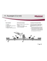
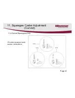
Page 39: ...11 Squeegee Curved 11 Page 39 ...

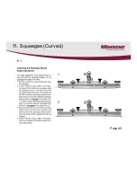
Page 40: ...11 Squeegee Curved 11 1 Page 40 ...

Page 41: ...5 3 between the angle and the fixed roller housing pos 7 Fig 5 3 to increase clearance or remove existing 1mm spacer from between the angle and the fixed roller housing in order to reduce the clearance Re insert the spacers removed from between the angle and the fixed roller housing again above the fixed roller housing to allow complete tightening of the screws 3mm 0 5 0 118 in 02 Page 41 ...

Page 42: ...ng the wheel height there should always be 5 washers on each wheel assembly in order fully tighten bolts Move washers from the top to the bottom of the bracket or visa versa when making adjustments See following page 11 3 Curved Squeegees Only 11 Squeegee Caster Adjustment Curved Page 42 ...

Page 43: ...11 4 Curved Squeegees Only Possible squeegee caster washer combinations 11 Squeegee Caster Adjustment Curved Page 43 ...

Page 44: ...ce of the batteries 3 Use appropriate filling devices when filling the batteries Do not use a garden hose or metal containers Flooding the batteries can flush the electrolyte out of the battery and shorten its life 4 Fill cells 3 8 to 1 2 of an inch above the separators Do not fill above the fill marker of the batteries Over filling can cause the electrolyte to percolate out onto the case while ch...

Page 45: ...e cases with a water displacement chemical or a silicone This will help break the flow of current across the case and increases the life of the battery Note The electrolyte on the surface of the case can cause A The batteries to discharge faster even while sitting and have a shorter run time B The battery charger to stay on for extended periods Thus causing an over charge condition and shortening ...

Page 46: ...cate that the batteries are weak or discharged A fully charged good battery should test in the good or green range of the meter Load testing can identify dead cells broken or disconnected plates weak cells and charge status This is good test however it can only detect these types of failures Most load testers require putting a load on the batteries for 10 seconds Load testing may not detect all sh...

Page 47: ...ccurate enough for this test are not recommended Fully charged batteries should read 1 265 and will decrease as batteries are discharged until they reach 1 120 This test should be done when batteries are charged and cooled Allow one hour or more to cool It can also be done after batteries are partially discharged if they are allowed to cool However you will not be able to detect the full capacity ...

Page 48: ...lls readings the greater the loss of run time For example if the readings are 1 265 1 265 and 1 225 in one 6 volt battery The low cell would be considered weak and greatly reduce the performance of the battery or shorter run time This battery would have a point 40 variation Batteries that have weakened cells in most cases it can still be used as long they continue provide adequate run time A batte...

Page 49: ...ged it uses one cycle The specific gravity will reflect the percentage of charge remaining in the battery 100 charge 1 265 or higher Specific Gravity 75 charge 1 225 Specific Gravity 50 charge 1 190 Specific Gravity 25 charge 1 120 Specific Gravity Note AGM Gel maintenance free batteries can not be tested with the hydrometer Do not attempt to open cell covers or caps Doing so will destroy the batt...

Page 50: ...hen transporting the machines on a trailer or truck always Tie down the machine securely Lower the brush head assembly completely to the floor Turn the machine off Failure to do the above may result in damage to the machine Page 50 ...

Page 51: ...itch Switch Off Switch On Switch Unload The key switch has 8 terminals Below shows the three different switch functions The black bars indicate the internal connection made by the switch in each position Page 51 ...

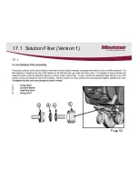
Page 52: ...17 1 Solution Filter Version 1 17 1 Page 52 ...

Page 53: ...ion Filter Version 2 1 The solution filter is located under the machine 2 The filter can be cleaned by unscrewing cap 3 Drain solution tank before cleaning filter Filter Location New Style Solution Filter Page 53 ...

Page 54: ...rolled 25 Volts Digital Volt Meter 18 Testing the Main Power Relay on the E17 E20 and E26ECO Note Measure the voltage across the B and the B coil terminals with the wires attached and the key switch turned on It should be about 24 volts Diode Page 54 ...

Page 55: ...gital Volt Meter 18 Testing the Main Power Relay on the E17 E20 and E26ECO Note Measure the voltage from a battery negative source to the B terminal of the main relay s coil to determined of the B is being supplied to the coil It should be 24 volts Batteries OR Page 55 ...

Page 56: ...ital Volt Meter 18 Testing the Main Power Relay on the E17 E20 and E26ECO Note Measure the voltage from the battery positive source to the B terminal of the main relay s coil to determined of the B is being supplied to the coil It should be 24 volts Batteries OR Page 56 ...

Page 57: ...ry B Controlled B Controlled 25 5 volts Digital Volt Meter 18 Testing the Main Power Relay on the E17 E20 and E26ECO Note Measure the voltage across the battery side across the B B terminals when the machine is under load Page 57 ...

Page 58: ...rolled 22 4 volts Volt Meter 18 Testing the Main Power Relay on the E17 E20 and E26ECO Note The voltage should be exactly the same as incoming battery side when the machine turned on and is under load motors are running The relay is defective Page 58 ...

Page 59: ...he forward or reverse position test in both positions Activate the drive lever The resistance should vary from 5K to Inf The resistance should change smoothly If not see Testing the Potentiometer Testing the Potentiometer Disconnect the potentiometer from the circuit With a ohm meter measure the resistance across the black orange wire and the black white wire The resistance should be 5K about 4 7 ...

Page 60: ...Test the switch that is connected to the red and white wires coming from the main harness The blue and black connection should test open until the switch is activated It should close when it is activated If it doesn t replace the switch 19 1 Trouble Shooting Traction Drive Switch Page 60 ...

Page 61: ... battery for this test with squeegee vacuum switch activated and driving the machine forward 4 The wires will need to be connected to terminal while doing test Note Lift the drive wheels off the floor before doing test The voltage should be 20 to 24 volts If not go to step 5 If the 20 to 24 volts is present test vacuum relay step 8 5 Remove the diode from the contactor and test with a multi meter ...

Page 62: ...inals on the vacuum relay It should read 0 zero volts When it is deactivated it should measure 24 volts 4 If not replace the relay Page 62 6 Retest for voltage across the vacuum coil small terminals with the squeegee switch and drive activated If the voltage is below the 18 volts replace the I drive controller If voltage is above continue testing the vacuum relay in step 7 Coil Terminals Contact T...

Page 63: ...tance Adjust shaft while testing Fig 3 1 Disconnect the potentiometer from circuit 2 Use ohm meter preferably an analog type to measure the resistance across the two outside terminals Fig 1 It should measure 5K 5 000 ohms 20 3 Measure the resistance from the center terminal to each outside terminal Fig 2 and Fig 3 The resistance should show a smooth change while turning the shaft on each Page 63 ...

Page 64: ...20 Notes Page 64 ...

Reviews: