background image

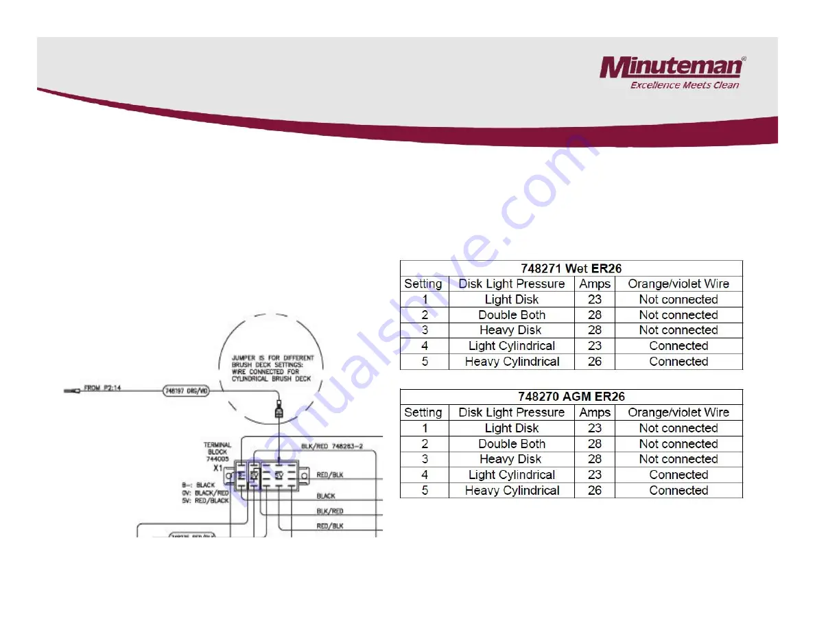
4.2 Brush Pressure Settings

The brush pressure range can be changed
when changing the type of deck on the ER26
and SC2426 models.
Connect the orange/violet wire into the
terminal block with red/black wire group for
cylindrical decks and unplug it for the disk
decks.
The terminal block is located below the Trio
controller on the ER26 and SC2426 models.

Brush Pressure Settings

Page 15

ER26 and SC26P Shown

Summary of Contents for ES2832

Page 1: ... ER26 ER2832 SCV2832E SCV2426 SCV280000 ES2832 Automatic Scrubbers Service Manual For the ER26 ER2832 SCV2832E SCV2426 SCV280000 ES2832 Automatic Scrubbers For Training Troubleshooting Adjustments Rev 11 2012 ...

Page 2: ... 6 Page 7 Page 8 Page 9 Page 10 Page 11 Page 12 Page 13 Page 14 Page 15 Page 16 17 Page 18 Page 19 22 1 Cautions 2 Maintenance Intervals 2 1 Customer Maintenance 2 2 Maintenance I after every 125 hours of operation 2 3 Maintenance II after every 250 hours of operation 2 4 Maintenance S after every 500 hours of operation minimum once per year 3 Service Mode 3 1 Service Mode SC280000 3 2 Service Mod...

Page 3: ...e 21 Page 25 Page 26 Page 27 29 Page 30 Page 40 42 Page 43 44 Page 45 Page 46 Page 47 Page 48 Page 49 5 2 Error Codes LED 6 Side Squeegee Adjustment cylindrical 6 1 Side Squeegee Adjustment disk 7 Rear Squeegee Adjustments 8 Replacing the Brush Actuator On SC2832 Models 9 Trouble Shooting the Code 8 Error 10 Testing the Throttle Potentiometer 11 Identifing the Cause of Trio Controllers Failures 12...

Page 4: ...Do not apply power directly to the motors without first disconnecting them from the controller circuit Page 4 Always disconnect the A C Cord from the outlet and and D C Cord from the battery pack before servicing the machine Except for making voltage and current measurements Before replacing or disconnecting any electrical componets disconnect the battery pack from the machine first Failure to do ...

Page 5: ...erformed by an authorized Minuteman Service Center in accordance with the machine specific system maintenance Maintenance Intervals In a modular structure the Minuteman System Maintenance determines the specific technical proceedures to be preformed and sets the time interval between the two maintenance cycles For each of the maintenance cycle the replaceable parts are determined as well Further d...

Page 6: ...2 1 Minuteman System Maintenance K Page 6 ...

Page 7: ...2 2 Minuteman System Maintenance I Page 7 ...

Page 8: ...2 3 Minuteman System Maintenance II Page 8 ...

Page 9: ...2 4 Minuteman System Maintenance S Page 9 ...

Page 10: ...pressing the top or lower part of the rocker switch To return the machine back to normal operation Turn the key switch off and back on The machine will reset The switch located below the seat behind the panel on the right side on the SCV2832E and ER2832 s The switch is located below the recovery tank on the ES2832 and CP2832 models Page 10 The switch is located behind the panel on the left side on...

Page 11: ...ing the brush pressure up and down arrows SC280000 Models Only Push and hold the brush pressure down button for 15 20 seconds Once it is in service mode You can raise and lower the deck buy pressing the brush pressure up and down arrows Page 11 To return the machine back to normal operation Turn the key switch off and back on The machine will reset ...

Page 12: ... the upper or lower part of the rocker switch SCV2426P Only The Service Mode Switch on the ER26 and SCV2426 is located next to the step on the front of the machine on the operator s left side Once it is in service mode the deck can raised and lowered by pressing the upper or lower part of the rocker switch Page 12 To return the machine back to normal operation Turn the key switch off and back on T...

Page 13: ... block is located below the Trio controller on the SCVs and below the control panel on the ES The brush pressure range can be changed when changing the type of deck on the SC2832E SC2426P CP2832 and ES2832 models Connect the orange violet wire into the terminal block with red black wire group for cylindrical decks and unplug it for the disk decks The terminal block is located below the Trio contro...

Page 14: ...it for the disk decks The terminal block is located below the Trio controller on the ER2832s Brush Pressure Settings The brush pressure range can be changed when changing the type of deck on the ER2832 models Connect the orange violet wire into the terminal block with red black wire group for cylindrical decks and unplug it for the disk decks The terminal block is located below the Trio controller...

Page 15: ... the ER26 and SC2426 models Connect the orange violet wire into the terminal block with red black wire group for cylindrical decks and unplug it for the disk decks The terminal block is located below the Trio controller on the ER26 and SC2426 models Brush Pressure Settings Page 15 ER26 and SC26P Shown ...

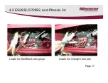
Page 16: ...cks Instructions 1 Remove the switch panel by removing the four screws 2 Locate the terminal block See Photograph It is now available to change the brush pressure settings in the field when changing brush decks on current production models of the Easy Scrub 28 and 32 No other modifications will be required Changing the brush pressure settings will only be required when changing the cylindrical ove...

Page 17: ...4 2 ES2832 CP2832 and Phoenix 34 Locate the Red Black wire group Locate the Orange Violet wire Page 17 ...

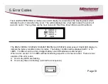
Page 18: ...ror Codes The ER26 ER2832 SC2832E SC2426P ES2862 and CP2832 models uses a 10 light LED display to indicate the battery condition and error codes The battery condition will be displayed with 1 to 10 LEDS 10 LEDs would be a fully charged battery one LED batteries are discharged When a error occurs 1 to 10 LEDS will flash indicating a specific error has occurred There are two aspects of the error cod...

Page 19: ...ENT OCCURRED Water Solenoid on Aux 4 exceeded 7 amp max current limit Check wiring or replace device S 1318 BEACON LIGHT CIRCUIT OVERLOAD olution Tank Empty signal from float switch Beacon light circuit Check for short or incorrect wiring 131C SOFT ALARM OVERCURRENT OCCURRED Alarm circuit exceeded 2 amp max current limit Check wiring or replace device 1321 AUX1 OVERCURRENT 2 OCCURRED Device connec...

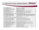
Page 20: ...heck for jammed Brushes or Deck or Brush motor short 7604 SOFT BRUSH INHIBIT Brush Inhibit signal is active 7605 BRUSH STARTUP OVERCURRENT DETECTION Possible Brush motor problem or shorted brush circuit wiring 7700 SOFT VACUUM MOTOR DISCONNECTED ERROR Check Vacuum Motor wiring and connectors 7701 SOFT VACUUM CURRENT FOLDBACK Too much Vac motor current Check for shorted Vac motor or wiring 7702 SOF...

Page 21: ...B02 IMPORTANT 0B0B TRIO TRIO HD can be damaged internally by shorting Batt to any of it s Inputs or Outputs Check Wiring Harness for shorts before installing a replacement Control 1704 If replacement control fails then replace Wiring Harness before installing any more Controls 1705 1706 1706 1800 1802 1B20 1B21 2102 2103 2D01 3100 Shorted Circuit Check For Shorts on the Brush and Drive Motor Circu...

Page 22: ...01 4 If Diagnostic Code is not cleared then replace TRIO TRIO HD control 3602 3603 3603 3608 3609 IMPORTANT 360A TRIO TRIO HD can be damaged internally by shorting Batt to any of it s Inputs or Outputs 360B Check Wiring Harness for shorts before installing a replacement Control 360C If replacement control fails then replace Wiring Harness before installing any more Controls 360D 360E 7501 Page 22 ...

Page 23: ... Charge the batteries Single flash Traction drive motor overload Has two levels soft warning and critical shut down Single flash Brush motor fault disconnected or over load Single flash Brush actuator overload Two flash Squeegee actuator overload Page 23 ...

Page 24: ...sh Off Isle Wand Activated Single flash Off Isle Wand Activated Si l fl h Th l i f l Single flash Throttle potentiometer fault Single flash Control fault check for loose connections to Single flash Control fault check for loose connections to the controller and or for a possible short circuit see Trouble Shooting the Code 8 Error Page 24 ...

Page 25: ...ank empty Riders only Two flash Not used 5 1 Table Error Codes LED Three flash Water solenoid fault Four flash Water pump fault Five flash Electric brake circuit fault Check all connections to the electric brake e mag Page 25 ...

Page 26: ...5 1 Table Error Codes LED Single flash High battery voltage Check all connections Ripple Throttle activated during start up Page 26 ...

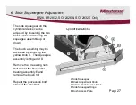
Page 27: ...eat the process on both sides of the machines B E ER26 ER2832 SCV2426 SCV2832E Only The side squeegees on the cylindrical decks can be adjusted by loosening the two black knobs and moving the squeegee assemble up or down The brush assembly may be accessed by removing the yellow knob C The squeegee assembly is hinged at D Remove the three wing nuts that mount the brush idler bearing assembly E and ...

Page 28: ...ts and moving the assembly up or down Repeat the process on both sides if needed Wing Nuts ER26 ER2832 SCV2426 SCV2832E Only The side squeegee assemblies can be adjusted by loosening the two wing nuts and moving the assembly up or down Repeat the process on both sides if needed Wing Nuts Squeegee Assembly Page 28 ...

Page 29: ...ion of the nuts until squeegee sets level to the floor Tighten the jam nuts to lock into position For ER26 and ER2832 Page 29 The pitch of the squeegee can be adjusted by loosening the jam nuts Adjust the position of the nuts until squeegee sets level to the floor Tighten the jam nuts to lock into position ...

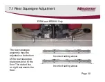
Page 30: ...ER26 and ER2832 Only The rear squeegee assembly must be adjusted so the bottom of the rear squeegee blade sets level to the floor The dotted line on right represents the floor Incorrect setting above Incorrect setting above Page 30 ...

Page 31: ...tween the angle and the fixed roller housing to increase clearance or remove existing 1mm spacer from between the angle and the fixed roller housing in order to reduce the clearance Re insert the spacers removed from between the angle and the fixed roller housing again above the fixed roller housing to allow complete tightening of the screws 3mm 0 5 0 118 in 02 Page 31 ...

Page 32: ...ers may be rearranged to change the height of the squeegee caster Note When adjusting the wheel height there should always be 5 washers on each wheel assembly in order fully tighten bolts Move washers from the top to the bottom of the bracket or visa versa when making adjustments See following page Page 32 ...

Page 33: ...ob Loosen the wing nuts before adjusting Tighten the wing nuts to lock into position Wing Nuts SCV2426 SCV2832E Only The pitch of the squeegee can be adjusted by turning the knob Loosen the wing nuts before adjusting Tighten the wing nuts to lock into position Adjustment Knob Page 33 ...

Page 34: ...7 5 Rear Squeegee Adjustment SCV2426 SCV2832E Only Page 34 ...

Page 35: ...7 6 Rear Squeegee Adjustment SCV2426 SCV2832E Only Page 35 ...

Page 36: ...own using the touch pad or rocker switch so that it gently rests on the mounting brackets All Versions Of SCV2832E and SC280000 With the 742712 2 Actuator Replacing the Brush Actuator on the SCV 28 or 32 1 Lower the brush deck so it gently rests on the floor 2 Remove the side squeegees 3 Remove the four bolts that mount the deck to the lift linkage 4 Unplug the electrical connector and the Quick C...

Page 37: ... off and back on 27 Test the machine 8 Replacing the Brush Actuator on the SCV 28 or 32 All Versions Of SCV2832E and SC280000 With the 742712 2 Actuator only 16 Slide the brush deck into position install the four mounting bolts and tighten Connect the brush motor connector and solution quick connector 17 Locate the black rubber removable plug on the right side of the actuator and remove 18 For mod...

Page 38: ...8 1 Actuator Adjustment 742712 2 only Page 38 ...

Page 39: ...econds and then release Plug the P2 connector back in with the machine still turned on Press the lower side of the service mode switch to lower the brush deck Page 39 With the machine turned off unplug the P2 connector on the controller Turn the machine on and press the service mode switch up to 30 seconds and then release Plug the P2 connector back in with the machine still turned on Press the lo...

Page 40: ...e of the machine Repair or clean if needed if needed 9 Trouble Shooting the Code 8 Error ER26 ER2832 ES2832 CP2832 SCV2426 and SC2832E Models 1 Disconnect one motor connector from the Trio controller at a time and disconnect the batteries for two minutes 2 Reconnect the battery pack and turn the machine with one motor disconnected 3 Repeat this process with each motor 4 If the code 8 disappears an...

Page 41: ...ould cause spikes and surges that could damage the Trio controller permanently 9 Trouble Shooting the Code 8 Error 9 Check for a disconnected or an open circuit or faulty potentiometer on the throttle or speed circuit The controller may not be detecting it in the circuit Do a continuity test See Testing the Throttle Control Potentiometer see section 10 10 If the code 8 always shows after completin...

Page 42: ...ence would indicate a problem in the connections 15 Repair or replace any parts needed before replacing controller 13 Test the two small wires on the Traction harness for resistance that go the electric brake E Mag The resistance should be 60 to 80 ohms Turn the steering wheel slowly in both directions until it stops several times Monitor the meter while turning The resistance should not change or...

Page 43: ...e across the red and white wire on the potentiometer assembly It should measure approximately 5K 5 thousand ohms 20 1 Check for a open or faulty potentiometer circuit 2 The throttle potentiometer resistance can be measured with an ohmmeter 3 Analog type meters are recommended for this test not digital 4 Locate the Trio controller Unplug the P3 connector the large white connector with 14 pins on th...

Page 44: ...go to 5K during the test the arm and the potentiometer may need to be adjusted to achieve it 9 Riders Only Measure resistance across the black and white wires on the potentiometer the resistance should be zero ohms with pedal on the riders in the neutral position When the pedal or knob is moved to the full throttle position in should be a smooth resistance change without dropping out It should mea...

Page 45: ...oller They should be exactly the same A 1 10 of a volt or more difference would indicate a problem in the connections 1 Check for loose or burnt connections on the controller batteries cables and the circuit breaker Make the sure the circuit breaker is not damaged burnt or cracked 2 Test the chassis drive motor harness for broken wires Disconnect the plug labeled Traction on the Trio controller Co...

Page 46: ...til the correct air gap is obtained The electric brake will work properly up to 0 15mm minimum air gap Page 46 The Electric brake must be checked periodically Clean the electric brake by using high pressure air to remove dust and dirt Verify the metal disk in the brake moves when pulling the arm away from the brake with a small amount of pressure Verify that the air gap with the electric brake mou...

Page 47: ...nged when it reaches to 1 1 mm thickness Page 47 Note The electric brake will work at 70 of battery power 25 2 volts and at 70 80 C 158 176 F electric brake working temperature It shouldn t exceed an air gap of maximum gap of 0 45 0 5 mm to work properly at this temperature When operated at 100 battery power and at room temperature the maximum air gap limit should not exceed 0 7mm ...

Page 48: ...12 2 Electric Brake Maintenance Adjustment Install the plastic water protection cap Part number Install the rubber seal not shown around the outside of the brake Page 48 ...

Page 49: ...13 Notes ...

Reviews: