


4
BRUSH INSTALLATION - REMOVAL
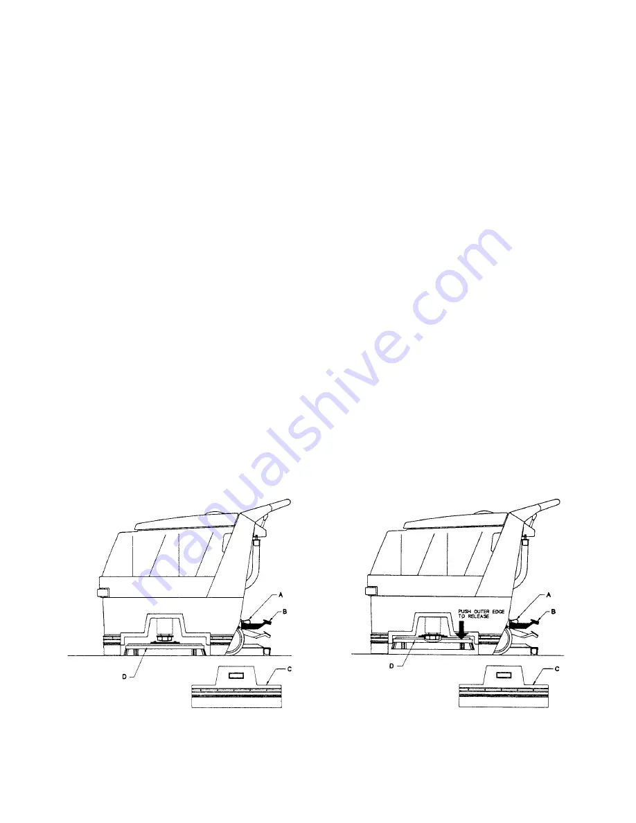
INSTALLATION - Figure 1
1. Disconnect power cable (mains) from machine.
2. Set brush assist lever (A) to rabbit.
3. Raise brush mechanism (B) to the “up” position by depressing pedal downward as shown.
4. Remove side skirt (C) by lifting up and away.
5. Center brush (D) under machine as shown lining up center
hex drive hub.
6. By releasing foot pedal (B) to lower brush mechanism, drive hub will engage.
REMOVAL - Figure 2
1. Disconnect power cable (mains) from machine.
2. Set brush assist lever (A) to rabbit.
3. Raise brush mechanism (B) to “up” position by depressing pedal downward as shown.
4. Remove side skirt (C) by lifting up and away.
5. Brush has snap-on push-off clutch plate. By pushing brush away from machine and from side it
will release brush assembly.
Fig. 1
Fig. 2
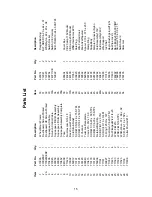
Summary of Contents for MC20115
Page 2: ......
Page 9: ...6 ...
Page 11: ...8 ...
Page 13: ...10 ...
Page 15: ...12 ...
Page 17: ...14 ...
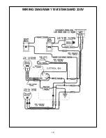
Page 21: ...18 WIRING DIAGRAM 115V STANDARD 230V ...
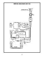
Page 22: ...19 WIRING DIAGRAM 230V CE ...


