
12
CONTROL CONSOLE
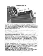
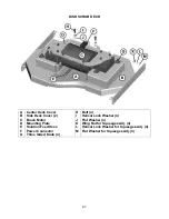
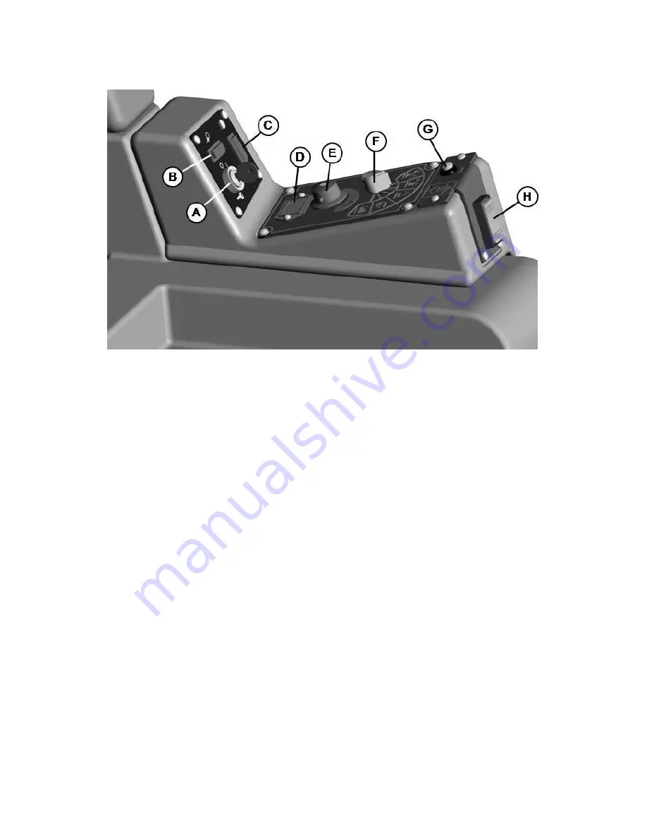
For operator ergonomics, the control console houses all the primary function controls in a
central area. The key switch and optional headlight and off-aisle wand switches are clustered in
the back portion of the console. The directional switch (forward/reverse) is located at the front of
the console for easy fingertip operation. The horn button, function selectors, and battery gauge
are located in the central part of the console.
KEY SWITCH
(A)
–
Controls the machine’s power (ON/OFF) with a key for safety. All
operational settings are retained even when the power is turned off and on. This also serves as
a reset switch when errors or faults occur.
OFF AISLE WAND SWITCH (OPTIONAL)
(B)
–
ON/OFF control for the water supply to the
wand and vacuum motor for the optional Off-Aisle Wand.
HEADLIGHT SWITCH (OPTIONAL)
(C)
–
ON/OFF control for the optional headlights.
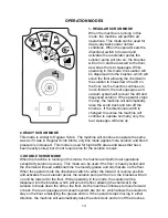
BATTERY GAUGE
(D)
- Displays the level of charge remaining in the machine’s batteries. The
gauge consists of 10 LEDs. (3 Green, 4 Amber, 3 Red) If the battery life is low, the battery
gauge bar icon will be flashing to inform the operator that the machine is almost out of power.
Once this signal is displayed, all functions will shut off, including transport mode. The operator
must then
turn the key switch OFF and then ON
to reset the machine. The machine will then
have only a few minutes left of reserve power to briefly use
Vacuum Only mode
to pick up any
remaining solution on the floor and
Transport mode
to return to the charging station. This gauge
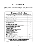
will also display a fault code if the system has an error. This code is represented by a specific
number of flashing LEDs.
See Fault/Diagnostic Codes for specific code information.
SOLUTION CONTROL KNOB
(E)
–
Adjusts the amount of solution being dispensed to the
floor while in one of the scrub modes. Turn the knob clockwise to increase the amount of
solution being dispensed. The amount of solution applied is variable to a maximum of 1 GPM.
MODE SELECTOR KNOB
(F)
–
This knob is used to select the desired operation mode of
the machine. See
Operation Modes for information about each mode.
HORN BUTTON
(G)
– Depressing
this button will activate the machine’s horn.
DIRECTIONAL SWITCH
(H)
–
Flipping this switch to the down position will set the machine
to move forward. Flipping it to the up position sets the machine to move in reverse.
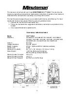
Summary of Contents for SCV 28/32
Page 1: ...SCV 28 32 RIDER SCRUBBER OPERATION SERVICE PARTS CARE ...
Page 3: ...3 ...
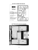
Page 19: ...19 BATTERY CONNECTION DIAGRAM BATTERIES INSTALLED WITH SPACERS ...
Page 34: ...34 EXPLODED VIEWS MAIN ASSEMBLY I ...
Page 35: ...35 MAIN ASSEMBLY I BOM ...
Page 36: ...36 MAIN ASSEMBLY II ...
Page 37: ...37 MAIN ASSEMBLY II BOM ...
Page 38: ...38 MAINFRAME ASSEMBLY I ...
Page 39: ...39 MAINFRAME ASSEMBLY II ...
Page 40: ...40 MAINFRAME ASSEMBLY II BOM ...
Page 41: ...41 FRONT DRIVE ASSEMBLY ...
Page 42: ...42 FRONT DRIVE ASSEMBLY BOM ...
Page 43: ...43 STEERING ASSEMBLY ...
Page 44: ...44 STEERING ASSEMBLY BOM ...
Page 45: ...45 SOLUTION TANK ASSEMBLY SEAT ASSEMBLY ...
Page 46: ...46 SOLUTION TANK ASSEMBLY SEAT ASSEMBLY BOM s ...
Page 47: ...47 ELECTRICAL PANEL ...
Page 48: ...48 CONSOLE ...
Page 49: ...49 RECOVERY TANK I ...
Page 50: ...50 RECOVERY TANK I BOM ...
Page 51: ...51 RECOVERY TANK II ...
Page 52: ...52 BATTERY BOX ASSEMBLY ...
Page 53: ...53 PUMP ASSEMBLY ...
Page 54: ...54 PUMP ASSEMBLY BOM ...
Page 55: ...55 REAR AXLE ASSEMBLY ...
Page 56: ...56 SQUEEGEE MECHANISM ASSEMBLY ...
Page 57: ...57 28 REAR SQUEEGEE ASSEMBLY ...
Page 58: ...58 28 REAR SQUEEGEE ASSEMBLY BOM ...
Page 59: ...59 32 REAR SQUEEGEE ASSEMBLY ...
Page 60: ...60 32 REAR SQUEEGEE ASSEMBLY BOM ...
Page 61: ...61 28 CYLINDRICAL SCRUBDECK ITEMS 1 32 ...
Page 62: ...62 28 CYLINDRICAL SCRUBDECK ITEMS 33 64 ...
Page 63: ...63 28 CYLINDRICAL SCRUBDECK BOM ...
Page 64: ...64 32 CYLINDRICAL SCRUBDECK ITEMS 1 32 ...
Page 65: ...65 32 CYLINDRICAL SCRUBDECK ITEMS 33 64 ...
Page 66: ...66 32 CYLINDRICAL SCRUBDECK BOM ...
Page 67: ...67 28 DISK SCRUBDECK ...
Page 68: ...68 28 DISK SCRUBDECK BOM ...
Page 69: ...69 32 DISK SCRUBDECK ...
Page 70: ...70 32 DISK SCRUBDECK BOM ...
Page 71: ...71 CYLINDRICAL SCRUBDECK SIDE SQUEEGEE LEFT SIDE ...
Page 72: ...72 CYLINDRICAL SCRUBDECK SIDE SQUEEGEE RIGHT SIDE ...
Page 73: ...73 DISK SCRUBDECK SIDE SQUEEGEE LEFT SIDE ...
Page 74: ...74 DISK SCRUBDECK SIDE SQUEEGEE RIGHT SIDE ...
Page 75: ...75 CYLINDRICAL SCRUBDECK AND ROLLER BUMPER MOUNTING ...
Page 76: ...76 SCV28CQP SCV32CQP BOM s ...
Page 77: ...77 DISK SCRUBDECK AND ROLLER BUMPER MOUNTING ...
Page 78: ...78 SCV28DQP SCV32DQP BOM s ...
Page 79: ...79 PLUMBING DIAGRAM ...
Page 80: ...80 WIRING DIAGRAMS TRIO CONNECTIONS ...
Page 81: ...81 P3 TRIO CONNECTIONS ...
Page 82: ...82 P2 TRIO CONNECTIONS ...
Page 83: ...83 WIRE COLORS CODES ...


