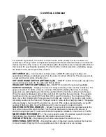
18
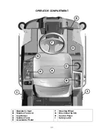
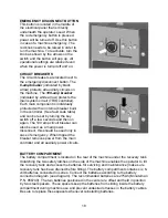
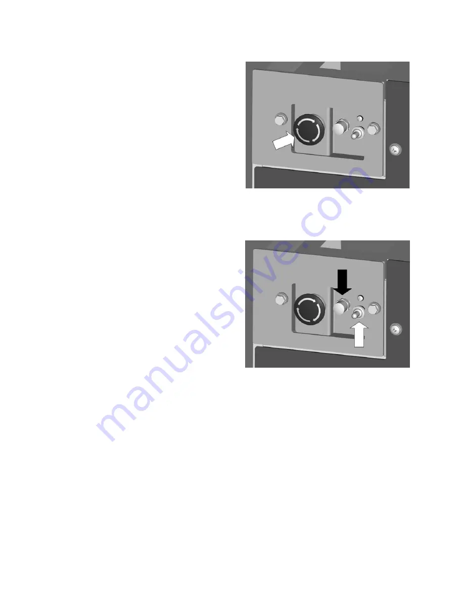
EMERGENCY DISCONNECT BUTTON
This button is located in the middle of
the electrical panel that is directly
underneath the operator’s seat. When
the
red
emergency button is pressed,
power will be turned off. Use this button
in case of a machine emergency. The
red knob needs to be raised in order to
run the machine. To reactivate, turn the
knob as shown by the arrows on the
switch and the button will pop up.
All
operational settings are retained even
when the power is turned off and on.
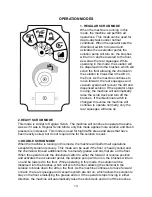
CIRCUIT BREAKERS
The circuit breakers are located next to
the emergency disconnect button. The
6-amp breaker
(indicated by black
arrow) protects all auxiliary circuits on
the machine. The
100-amp breaker
(indicated by white arrow) protects the
main system circuit (TRIO controller).
Each main component is individually
protected with an internal breaker built-
in the controller. (See fault code table)
and can be reset by turning the key
switch off a few seconds and then on
again. The 100 amp circuit breaker can
also be used as a main power
disconnect, this should be used only in
case of emergency. When tripped the
breaker removes power from the main
controller and all auxiliary power circuits.
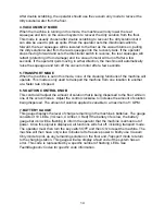
BATTERY COMPARTMENT
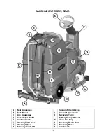
The battery compartment is located on the rear of the machine under the recovery tank.
Unlatching the two safety latches on the side of the machine enables the operator to tilt
the recovery tank and access the batteries for servicing and maintenance (make sure
recovery tank has been drained before tilting). The battery compartment contains six, 6-
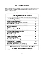
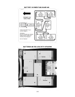
volt batteries connected in series. Connect the batteries according to the battery
connection diagram (
see diagram
). The recommended batteries are 275Ah (Minuteman
P.N. 956740). The two batteries positioned in the center are offset and held in position
by two steel spacers. These spacers keep the batteries from sliding inside the battery
compartment during machine use and prevent undesired stresses in the battery cables.
Be sure to replace these spacers whenever reinstalling batteries.
Summary of Contents for SCV 28/32
Page 1: ...SCV 28 32 RIDER SCRUBBER OPERATION SERVICE PARTS CARE ...
Page 3: ...3 ...
Page 19: ...19 BATTERY CONNECTION DIAGRAM BATTERIES INSTALLED WITH SPACERS ...
Page 34: ...34 EXPLODED VIEWS MAIN ASSEMBLY I ...
Page 35: ...35 MAIN ASSEMBLY I BOM ...
Page 36: ...36 MAIN ASSEMBLY II ...
Page 37: ...37 MAIN ASSEMBLY II BOM ...
Page 38: ...38 MAINFRAME ASSEMBLY I ...
Page 39: ...39 MAINFRAME ASSEMBLY II ...
Page 40: ...40 MAINFRAME ASSEMBLY II BOM ...
Page 41: ...41 FRONT DRIVE ASSEMBLY ...
Page 42: ...42 FRONT DRIVE ASSEMBLY BOM ...
Page 43: ...43 STEERING ASSEMBLY ...
Page 44: ...44 STEERING ASSEMBLY BOM ...
Page 45: ...45 SOLUTION TANK ASSEMBLY SEAT ASSEMBLY ...
Page 46: ...46 SOLUTION TANK ASSEMBLY SEAT ASSEMBLY BOM s ...
Page 47: ...47 ELECTRICAL PANEL ...
Page 48: ...48 CONSOLE ...
Page 49: ...49 RECOVERY TANK I ...
Page 50: ...50 RECOVERY TANK I BOM ...
Page 51: ...51 RECOVERY TANK II ...
Page 52: ...52 BATTERY BOX ASSEMBLY ...
Page 53: ...53 PUMP ASSEMBLY ...
Page 54: ...54 PUMP ASSEMBLY BOM ...
Page 55: ...55 REAR AXLE ASSEMBLY ...
Page 56: ...56 SQUEEGEE MECHANISM ASSEMBLY ...
Page 57: ...57 28 REAR SQUEEGEE ASSEMBLY ...
Page 58: ...58 28 REAR SQUEEGEE ASSEMBLY BOM ...
Page 59: ...59 32 REAR SQUEEGEE ASSEMBLY ...
Page 60: ...60 32 REAR SQUEEGEE ASSEMBLY BOM ...
Page 61: ...61 28 CYLINDRICAL SCRUBDECK ITEMS 1 32 ...
Page 62: ...62 28 CYLINDRICAL SCRUBDECK ITEMS 33 64 ...
Page 63: ...63 28 CYLINDRICAL SCRUBDECK BOM ...
Page 64: ...64 32 CYLINDRICAL SCRUBDECK ITEMS 1 32 ...
Page 65: ...65 32 CYLINDRICAL SCRUBDECK ITEMS 33 64 ...
Page 66: ...66 32 CYLINDRICAL SCRUBDECK BOM ...
Page 67: ...67 28 DISK SCRUBDECK ...
Page 68: ...68 28 DISK SCRUBDECK BOM ...
Page 69: ...69 32 DISK SCRUBDECK ...
Page 70: ...70 32 DISK SCRUBDECK BOM ...
Page 71: ...71 CYLINDRICAL SCRUBDECK SIDE SQUEEGEE LEFT SIDE ...
Page 72: ...72 CYLINDRICAL SCRUBDECK SIDE SQUEEGEE RIGHT SIDE ...
Page 73: ...73 DISK SCRUBDECK SIDE SQUEEGEE LEFT SIDE ...
Page 74: ...74 DISK SCRUBDECK SIDE SQUEEGEE RIGHT SIDE ...
Page 75: ...75 CYLINDRICAL SCRUBDECK AND ROLLER BUMPER MOUNTING ...
Page 76: ...76 SCV28CQP SCV32CQP BOM s ...
Page 77: ...77 DISK SCRUBDECK AND ROLLER BUMPER MOUNTING ...
Page 78: ...78 SCV28DQP SCV32DQP BOM s ...
Page 79: ...79 PLUMBING DIAGRAM ...
Page 80: ...80 WIRING DIAGRAMS TRIO CONNECTIONS ...
Page 81: ...81 P3 TRIO CONNECTIONS ...
Page 82: ...82 P2 TRIO CONNECTIONS ...
Page 83: ...83 WIRE COLORS CODES ...

