20
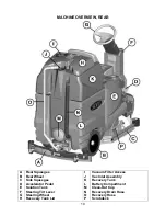
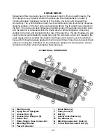
SCRUB DECKS
Minuteman offers two deck types (
Cylindrical and Disc
) to fit your specific needs. The
SCV design is very dynamic wherein the decks are interchangeable in a matter of
minutes whenever necessary (removal of four bolts, one hose, and one electrical
connection). The
cylindrical brush deck
has five built-in spray jets to uniformly dispense
cleaning solution on the floor and a wet sweeping debris tray to collect loose objects on
the floor.
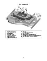
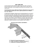
The disc brush deck
dispenses cleaning solution through the two center hubs
and the solution is contained within the bristle area for efficient agitation of cleaning
solution to the floor and channeled to the rear of the machine. The disc brushes are also
easily removed and installed by easily removing the side deck covers and releasing the
quick release clamp. Another nice feature that these scrub decks have is the ability to
have uniform brush pressure applied to the floor at all times. Since the scrub deck brush
pressure is computer controlled, it will automatically adjust and compensate to uneven
contours on the floor while maintaining brush pressure.
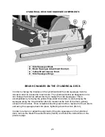
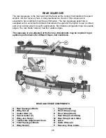
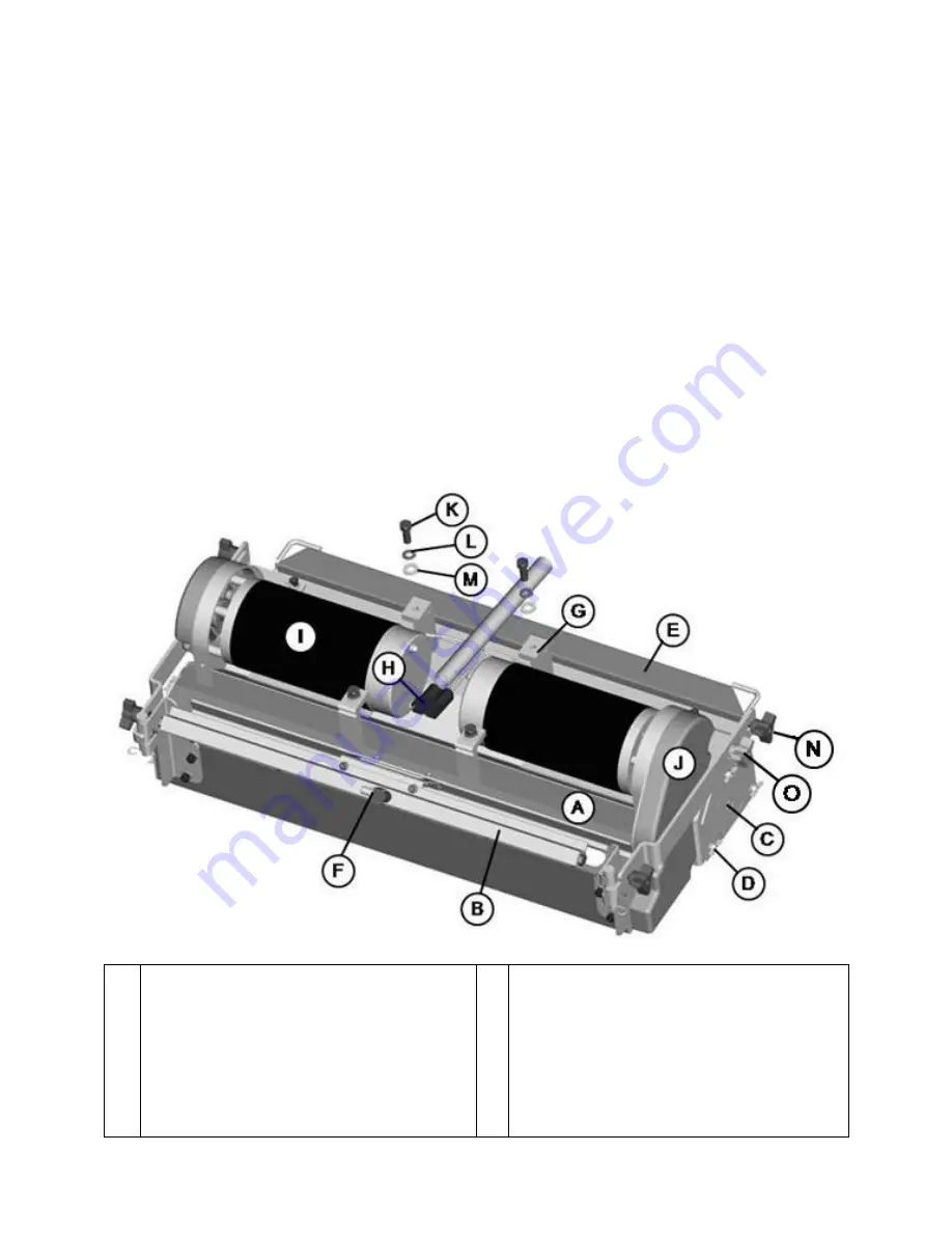
CYLINDRICAL SCRUB DECK
A
B
C
D
E
F
G
H
Main Housing
Spray Bar w/ Sprayjets
Access Door (2)
Access Door Wingnut (6)
Debris Box
Water Supply Hose Connection
Mounting Bracket
Power Connector
I
J
K
L
M
N
O
Brush Motor (2)
Pulley Cover (2)
Bolt (4)
Helical Lock Washer (4)
Flat Washer (4)
Black Squeegee Adj. Knob (4)
Yellow Brush Access Knob (2)
Summary of Contents for SCV 28/32
Page 1: ...SCV 28 32 RIDER SCRUBBER OPERATION SERVICE PARTS CARE ...
Page 3: ...3 ...
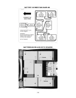
Page 19: ...19 BATTERY CONNECTION DIAGRAM BATTERIES INSTALLED WITH SPACERS ...
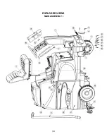
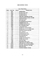
Page 34: ...34 EXPLODED VIEWS MAIN ASSEMBLY I ...
Page 35: ...35 MAIN ASSEMBLY I BOM ...
Page 36: ...36 MAIN ASSEMBLY II ...
Page 37: ...37 MAIN ASSEMBLY II BOM ...
Page 38: ...38 MAINFRAME ASSEMBLY I ...
Page 39: ...39 MAINFRAME ASSEMBLY II ...
Page 40: ...40 MAINFRAME ASSEMBLY II BOM ...
Page 41: ...41 FRONT DRIVE ASSEMBLY ...
Page 42: ...42 FRONT DRIVE ASSEMBLY BOM ...
Page 43: ...43 STEERING ASSEMBLY ...
Page 44: ...44 STEERING ASSEMBLY BOM ...
Page 45: ...45 SOLUTION TANK ASSEMBLY SEAT ASSEMBLY ...
Page 46: ...46 SOLUTION TANK ASSEMBLY SEAT ASSEMBLY BOM s ...
Page 47: ...47 ELECTRICAL PANEL ...
Page 48: ...48 CONSOLE ...
Page 49: ...49 RECOVERY TANK I ...
Page 50: ...50 RECOVERY TANK I BOM ...
Page 51: ...51 RECOVERY TANK II ...
Page 52: ...52 BATTERY BOX ASSEMBLY ...
Page 53: ...53 PUMP ASSEMBLY ...
Page 54: ...54 PUMP ASSEMBLY BOM ...
Page 55: ...55 REAR AXLE ASSEMBLY ...
Page 56: ...56 SQUEEGEE MECHANISM ASSEMBLY ...
Page 57: ...57 28 REAR SQUEEGEE ASSEMBLY ...
Page 58: ...58 28 REAR SQUEEGEE ASSEMBLY BOM ...
Page 59: ...59 32 REAR SQUEEGEE ASSEMBLY ...
Page 60: ...60 32 REAR SQUEEGEE ASSEMBLY BOM ...
Page 61: ...61 28 CYLINDRICAL SCRUBDECK ITEMS 1 32 ...
Page 62: ...62 28 CYLINDRICAL SCRUBDECK ITEMS 33 64 ...
Page 63: ...63 28 CYLINDRICAL SCRUBDECK BOM ...
Page 64: ...64 32 CYLINDRICAL SCRUBDECK ITEMS 1 32 ...
Page 65: ...65 32 CYLINDRICAL SCRUBDECK ITEMS 33 64 ...
Page 66: ...66 32 CYLINDRICAL SCRUBDECK BOM ...
Page 67: ...67 28 DISK SCRUBDECK ...
Page 68: ...68 28 DISK SCRUBDECK BOM ...
Page 69: ...69 32 DISK SCRUBDECK ...
Page 70: ...70 32 DISK SCRUBDECK BOM ...
Page 71: ...71 CYLINDRICAL SCRUBDECK SIDE SQUEEGEE LEFT SIDE ...
Page 72: ...72 CYLINDRICAL SCRUBDECK SIDE SQUEEGEE RIGHT SIDE ...
Page 73: ...73 DISK SCRUBDECK SIDE SQUEEGEE LEFT SIDE ...
Page 74: ...74 DISK SCRUBDECK SIDE SQUEEGEE RIGHT SIDE ...
Page 75: ...75 CYLINDRICAL SCRUBDECK AND ROLLER BUMPER MOUNTING ...
Page 76: ...76 SCV28CQP SCV32CQP BOM s ...
Page 77: ...77 DISK SCRUBDECK AND ROLLER BUMPER MOUNTING ...
Page 78: ...78 SCV28DQP SCV32DQP BOM s ...
Page 79: ...79 PLUMBING DIAGRAM ...
Page 80: ...80 WIRING DIAGRAMS TRIO CONNECTIONS ...
Page 81: ...81 P3 TRIO CONNECTIONS ...
Page 82: ...82 P2 TRIO CONNECTIONS ...
Page 83: ...83 WIRE COLORS CODES ...


