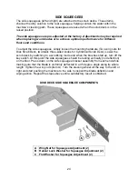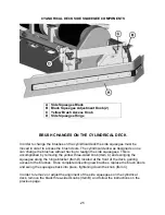
23
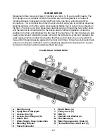
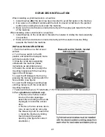
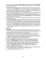
d. Align the notches on the brush with the drive pins on the hub.
e. Push the brush all the way in until it bottoms out.
f. Insert the access door hub into the other end of the brush.
g. Reinstall the wing nuts and yellow 3 sided knobs and tighten.
IMPORTANT NOTE WHEN INTERCHANGING SCRUB DECKS
As previously mentioned, the scrub deck brush pressure is computer controlled.
However, when interchanging the two types of decks, an additional step must be taken
to ensure that the controller correctly compensates the pressure for the type of deck
that is currently installed.
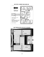
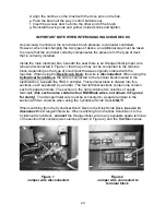
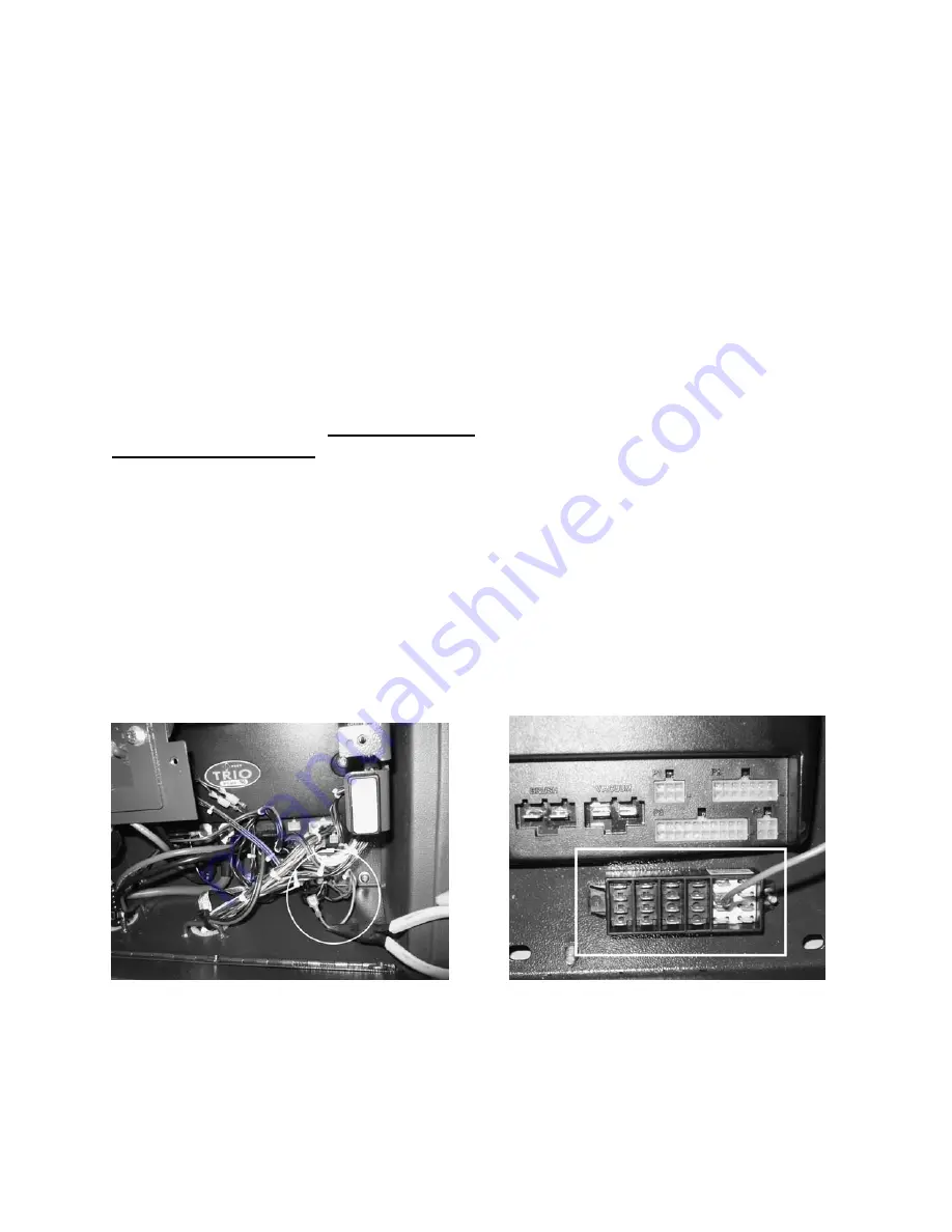
Inside the main electrical box, beneath the seat there is an Orange/Violet jumper wire
(shown disconnected in Figure 1) that may or may not be connected to the terminal
block, depending on the type of scrub deck that was originally ordered with the
machine. When using the
Disk Scrub Deck
, the wire is
disconnected
. When using the
Cylindrical Scrub Deck
, the wire is connected to the terminal block located in the
electrical box, beneath the TRIO Controller. This terminal block is divided into five
sections, each separated by a divider. The four leftmost sections contain one column
each of spade terminals. The section on the right contains two columns of spade
terminals (
this section also contains four Red/Black wires, not shown in Figure 2
for clarity
). The Orange/Violet wire must be connected to a spade terminal in the
section with two columns when using the Cylindrical Scrub Deck
ONLY!
When switching from the Cylindrical Scrub Deck to the Disk Scrub Deck,
be sure to
disconnect
the Orange/Violet wire. When switching from the Disk Scrub Deck to the
Cylindrical Scrub Deck,
connect
the Orange/Violet wire to any available spade terminal
in the section that contains two columns (shown in Figure 2) and the Red/Black wires.
Figure 1 Figure 2
Jumper wire disconnected Jumper wire connected to
terminal block
Summary of Contents for SCV 28/32
Page 1: ...SCV 28 32 RIDER SCRUBBER OPERATION SERVICE PARTS CARE ...
Page 3: ...3 ...
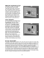
Page 19: ...19 BATTERY CONNECTION DIAGRAM BATTERIES INSTALLED WITH SPACERS ...
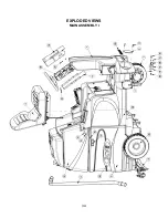
Page 34: ...34 EXPLODED VIEWS MAIN ASSEMBLY I ...
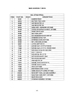
Page 35: ...35 MAIN ASSEMBLY I BOM ...
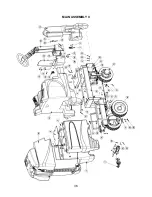
Page 36: ...36 MAIN ASSEMBLY II ...
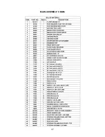
Page 37: ...37 MAIN ASSEMBLY II BOM ...
Page 38: ...38 MAINFRAME ASSEMBLY I ...
Page 39: ...39 MAINFRAME ASSEMBLY II ...
Page 40: ...40 MAINFRAME ASSEMBLY II BOM ...
Page 41: ...41 FRONT DRIVE ASSEMBLY ...
Page 42: ...42 FRONT DRIVE ASSEMBLY BOM ...
Page 43: ...43 STEERING ASSEMBLY ...
Page 44: ...44 STEERING ASSEMBLY BOM ...
Page 45: ...45 SOLUTION TANK ASSEMBLY SEAT ASSEMBLY ...
Page 46: ...46 SOLUTION TANK ASSEMBLY SEAT ASSEMBLY BOM s ...
Page 47: ...47 ELECTRICAL PANEL ...
Page 48: ...48 CONSOLE ...
Page 49: ...49 RECOVERY TANK I ...
Page 50: ...50 RECOVERY TANK I BOM ...
Page 51: ...51 RECOVERY TANK II ...
Page 52: ...52 BATTERY BOX ASSEMBLY ...
Page 53: ...53 PUMP ASSEMBLY ...
Page 54: ...54 PUMP ASSEMBLY BOM ...
Page 55: ...55 REAR AXLE ASSEMBLY ...
Page 56: ...56 SQUEEGEE MECHANISM ASSEMBLY ...
Page 57: ...57 28 REAR SQUEEGEE ASSEMBLY ...
Page 58: ...58 28 REAR SQUEEGEE ASSEMBLY BOM ...
Page 59: ...59 32 REAR SQUEEGEE ASSEMBLY ...
Page 60: ...60 32 REAR SQUEEGEE ASSEMBLY BOM ...
Page 61: ...61 28 CYLINDRICAL SCRUBDECK ITEMS 1 32 ...
Page 62: ...62 28 CYLINDRICAL SCRUBDECK ITEMS 33 64 ...
Page 63: ...63 28 CYLINDRICAL SCRUBDECK BOM ...
Page 64: ...64 32 CYLINDRICAL SCRUBDECK ITEMS 1 32 ...
Page 65: ...65 32 CYLINDRICAL SCRUBDECK ITEMS 33 64 ...
Page 66: ...66 32 CYLINDRICAL SCRUBDECK BOM ...
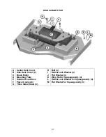
Page 67: ...67 28 DISK SCRUBDECK ...
Page 68: ...68 28 DISK SCRUBDECK BOM ...
Page 69: ...69 32 DISK SCRUBDECK ...
Page 70: ...70 32 DISK SCRUBDECK BOM ...
Page 71: ...71 CYLINDRICAL SCRUBDECK SIDE SQUEEGEE LEFT SIDE ...
Page 72: ...72 CYLINDRICAL SCRUBDECK SIDE SQUEEGEE RIGHT SIDE ...
Page 73: ...73 DISK SCRUBDECK SIDE SQUEEGEE LEFT SIDE ...
Page 74: ...74 DISK SCRUBDECK SIDE SQUEEGEE RIGHT SIDE ...
Page 75: ...75 CYLINDRICAL SCRUBDECK AND ROLLER BUMPER MOUNTING ...
Page 76: ...76 SCV28CQP SCV32CQP BOM s ...
Page 77: ...77 DISK SCRUBDECK AND ROLLER BUMPER MOUNTING ...
Page 78: ...78 SCV28DQP SCV32DQP BOM s ...
Page 79: ...79 PLUMBING DIAGRAM ...
Page 80: ...80 WIRING DIAGRAMS TRIO CONNECTIONS ...
Page 81: ...81 P3 TRIO CONNECTIONS ...
Page 82: ...82 P2 TRIO CONNECTIONS ...
Page 83: ...83 WIRE COLORS CODES ...

