24
SIDE SQUEEGEES
The side squeegees (left and right) are attached to the scrub decks. These items
channel the dirty solution to the rear squeegee, helping contain the water within the
machine’s cleaning path. These squeegees are raised when the scrub deck is in the
raised position.
The side squeegees are pre-adjusted at the factory. Adjustments may be required
when replacing worn blades or to achieve optimum performance for different
floors and conditions.
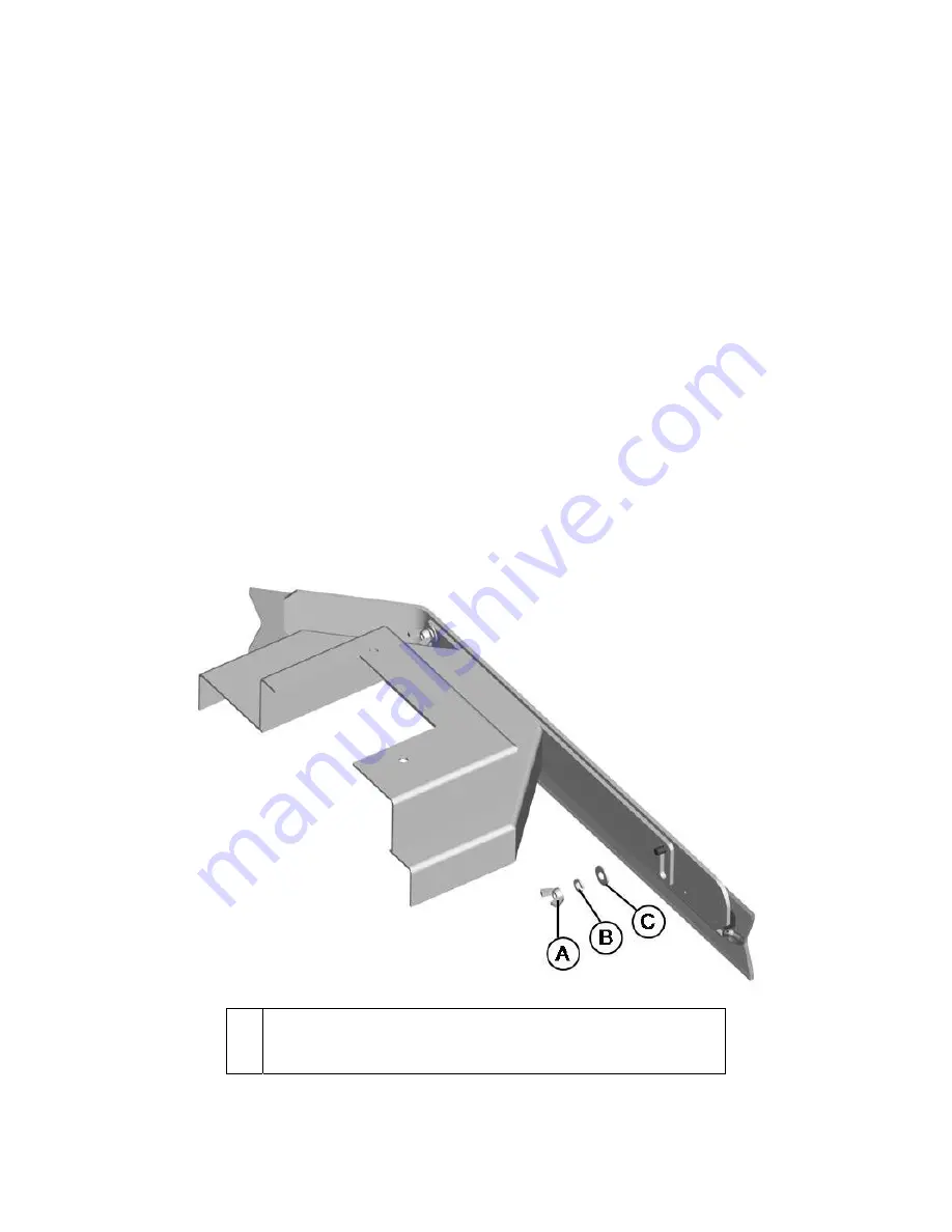
To adjust the side squeegees, simply loosen the mounting hardware (Two wing nuts for
Disk Scrub Deck, two black three-sided knobs for Cylindrical Scrub Deck). Lower the
scrub deck by switching to a scrubbing mode and when the brushes start up, turn off the
key switch. At this point the side squeegees should be resting vertically (no deflection)
on the floor. Press down on the side squeegee bracket assembly from each end while
making sure that the blade is uniformly deflected in a 45 degree angle along its whole
length. Tighten the wing nuts (item A). Turn the steering wheel all the way to the left or
right and start pushing the machine to the side to inspect the blade deflection and
wiping action. Repeat the steps above until a satisfactory result is obtained.
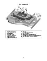
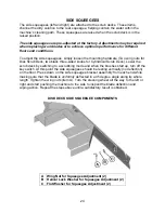
DISK DECK SIDE SQUEEGEE COMPONENTS
A
B
C
Wing Nut for Squeegee Adjustment (2)
Helical Lock Washer for Squeegee Adjustment (2)
Flat Washer for Squeegee Adjustment (2)
Summary of Contents for SCV 28/32
Page 1: ...SCV 28 32 RIDER SCRUBBER OPERATION SERVICE PARTS CARE ...
Page 3: ...3 ...
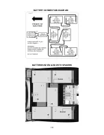
Page 19: ...19 BATTERY CONNECTION DIAGRAM BATTERIES INSTALLED WITH SPACERS ...
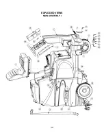
Page 34: ...34 EXPLODED VIEWS MAIN ASSEMBLY I ...
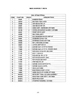
Page 35: ...35 MAIN ASSEMBLY I BOM ...
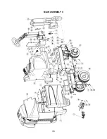
Page 36: ...36 MAIN ASSEMBLY II ...
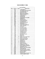
Page 37: ...37 MAIN ASSEMBLY II BOM ...
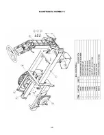
Page 38: ...38 MAINFRAME ASSEMBLY I ...
Page 39: ...39 MAINFRAME ASSEMBLY II ...
Page 40: ...40 MAINFRAME ASSEMBLY II BOM ...
Page 41: ...41 FRONT DRIVE ASSEMBLY ...
Page 42: ...42 FRONT DRIVE ASSEMBLY BOM ...
Page 43: ...43 STEERING ASSEMBLY ...
Page 44: ...44 STEERING ASSEMBLY BOM ...
Page 45: ...45 SOLUTION TANK ASSEMBLY SEAT ASSEMBLY ...
Page 46: ...46 SOLUTION TANK ASSEMBLY SEAT ASSEMBLY BOM s ...
Page 47: ...47 ELECTRICAL PANEL ...
Page 48: ...48 CONSOLE ...
Page 49: ...49 RECOVERY TANK I ...
Page 50: ...50 RECOVERY TANK I BOM ...
Page 51: ...51 RECOVERY TANK II ...
Page 52: ...52 BATTERY BOX ASSEMBLY ...
Page 53: ...53 PUMP ASSEMBLY ...
Page 54: ...54 PUMP ASSEMBLY BOM ...
Page 55: ...55 REAR AXLE ASSEMBLY ...
Page 56: ...56 SQUEEGEE MECHANISM ASSEMBLY ...
Page 57: ...57 28 REAR SQUEEGEE ASSEMBLY ...
Page 58: ...58 28 REAR SQUEEGEE ASSEMBLY BOM ...
Page 59: ...59 32 REAR SQUEEGEE ASSEMBLY ...
Page 60: ...60 32 REAR SQUEEGEE ASSEMBLY BOM ...
Page 61: ...61 28 CYLINDRICAL SCRUBDECK ITEMS 1 32 ...
Page 62: ...62 28 CYLINDRICAL SCRUBDECK ITEMS 33 64 ...
Page 63: ...63 28 CYLINDRICAL SCRUBDECK BOM ...
Page 64: ...64 32 CYLINDRICAL SCRUBDECK ITEMS 1 32 ...
Page 65: ...65 32 CYLINDRICAL SCRUBDECK ITEMS 33 64 ...
Page 66: ...66 32 CYLINDRICAL SCRUBDECK BOM ...
Page 67: ...67 28 DISK SCRUBDECK ...
Page 68: ...68 28 DISK SCRUBDECK BOM ...
Page 69: ...69 32 DISK SCRUBDECK ...
Page 70: ...70 32 DISK SCRUBDECK BOM ...
Page 71: ...71 CYLINDRICAL SCRUBDECK SIDE SQUEEGEE LEFT SIDE ...
Page 72: ...72 CYLINDRICAL SCRUBDECK SIDE SQUEEGEE RIGHT SIDE ...
Page 73: ...73 DISK SCRUBDECK SIDE SQUEEGEE LEFT SIDE ...
Page 74: ...74 DISK SCRUBDECK SIDE SQUEEGEE RIGHT SIDE ...
Page 75: ...75 CYLINDRICAL SCRUBDECK AND ROLLER BUMPER MOUNTING ...
Page 76: ...76 SCV28CQP SCV32CQP BOM s ...
Page 77: ...77 DISK SCRUBDECK AND ROLLER BUMPER MOUNTING ...
Page 78: ...78 SCV28DQP SCV32DQP BOM s ...
Page 79: ...79 PLUMBING DIAGRAM ...
Page 80: ...80 WIRING DIAGRAMS TRIO CONNECTIONS ...
Page 81: ...81 P3 TRIO CONNECTIONS ...
Page 82: ...82 P2 TRIO CONNECTIONS ...
Page 83: ...83 WIRE COLORS CODES ...

