30
12. To stop scrubbing, select the
Transport mode
. This will automatically stop the
Solution
Flow
, raise the
Scrub deck
, and raise the
Rear squeegee
(there is a 15 second delay
for the vacuum motor).
13. Drive the SCV to a designated dirty water disposal area and empty the Recovery tank.
To empty, remove the
Drain hose
from its storage hanger. Unscrew the plug and hold
the hose end above the water level in the tank to avoid sudden, uncontrolled flow of dirty
water. With the plug completely off, carefully direct the water flow to the desired drain.
Reinsert the plug and tighten and return to its storage hanger.
14. The recovery tank should be rinsed out to remove solids in the tank. Open the
Cleanout
cap
to remove the
Stopper
plug.
Tilt the recovery tank (similar to accessing the
batteries) and clean the sludge that has settled in the sump area by either back flushing
or by scraping it out. Be sure to tightly secure the
Stopper
plug
and cleanout cap before
continuing to operate the scrubber.
15. Refill the solution tank and continue scrubbing until the job is done or when the machine
runs out of power.
16.
The
battery gauge LEDs
will flash to signal the operator that the machine is almost out
of power. Once this signal is displayed to the operator,
all functions will shut off
(brush
will turn off and the scrub deck will raise up, water flow will cease, the rear squeegee will
raise up and the vacuum motor will turn off) including the transport mode. The operator
has to turn the
key switch OFF and then, ON to reset
the machine.
The machine will
then have only a few minutes left of reserve power to briefly use
Vacuum Only mode
to pick up any remaining solution on the floor and
Transport mode
to return to the
charging station.
AFTER USE:
1. When finished scrubbing, select the
Transport mode, all functions will shut off
(brush
will turn off and the scrub deck will raise up, water flow will cease, the rear squeegee will
raise up and the vacuum motor will turn off). Drive the machine to a service area for
daily maintenance and review items that may need service.
2. Empty the solution tank, by directly opening the
Garden hose valve
underneath the
machine into a drain on the floor or use a garden hose and attach it to the fitting to
remotely drain the solution tank. Rinse the tank with clean water to prevent any build-up
of dried up chemicals that could cause clogging in the plumbing.
3. Empty the recovery tank as described on line
15
and
16
.
4. Remove the
brushes
or pad holders and rinse them in warm water and hang to dry.
5. Remove the
rear
squeegee
, rinse with warm water and reinstall after cleaning.
6. Remove the
side
squeegees
, rinse with warm water and remove the
debris box
(cylindrical system only) and clean thoroughly. The debris box can be removed from
either side of the machine by tilting the box up and away from the housing and then
pulling it out. Reinstall the debris box and side squeegees after cleaning.
7. Check the
maintenance schedule
on the next page and perform any required
maintenance before storing the machine.
8. Store the machine indoors in a clean dry place. Keep from freezing. Leave solution and
recovery tank lids open for ventilation to prevent odor build-up.
9. Turn
Key switch OFF (O)
and remove key.
Summary of Contents for SCV 28/32
Page 1: ...SCV 28 32 RIDER SCRUBBER OPERATION SERVICE PARTS CARE ...
Page 3: ...3 ...
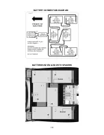
Page 19: ...19 BATTERY CONNECTION DIAGRAM BATTERIES INSTALLED WITH SPACERS ...
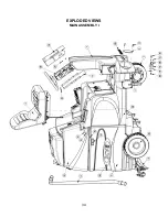
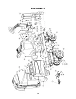
Page 34: ...34 EXPLODED VIEWS MAIN ASSEMBLY I ...
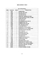
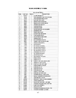
Page 35: ...35 MAIN ASSEMBLY I BOM ...
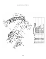
Page 36: ...36 MAIN ASSEMBLY II ...
Page 37: ...37 MAIN ASSEMBLY II BOM ...
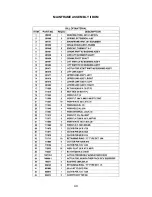
Page 38: ...38 MAINFRAME ASSEMBLY I ...
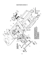
Page 39: ...39 MAINFRAME ASSEMBLY II ...
Page 40: ...40 MAINFRAME ASSEMBLY II BOM ...
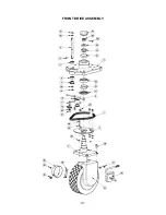
Page 41: ...41 FRONT DRIVE ASSEMBLY ...
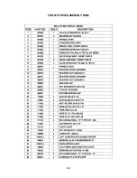
Page 42: ...42 FRONT DRIVE ASSEMBLY BOM ...
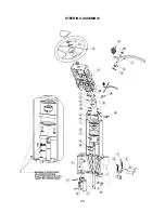
Page 43: ...43 STEERING ASSEMBLY ...
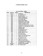
Page 44: ...44 STEERING ASSEMBLY BOM ...
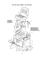
Page 45: ...45 SOLUTION TANK ASSEMBLY SEAT ASSEMBLY ...
Page 46: ...46 SOLUTION TANK ASSEMBLY SEAT ASSEMBLY BOM s ...
Page 47: ...47 ELECTRICAL PANEL ...
Page 48: ...48 CONSOLE ...
Page 49: ...49 RECOVERY TANK I ...
Page 50: ...50 RECOVERY TANK I BOM ...
Page 51: ...51 RECOVERY TANK II ...
Page 52: ...52 BATTERY BOX ASSEMBLY ...
Page 53: ...53 PUMP ASSEMBLY ...
Page 54: ...54 PUMP ASSEMBLY BOM ...
Page 55: ...55 REAR AXLE ASSEMBLY ...
Page 56: ...56 SQUEEGEE MECHANISM ASSEMBLY ...
Page 57: ...57 28 REAR SQUEEGEE ASSEMBLY ...
Page 58: ...58 28 REAR SQUEEGEE ASSEMBLY BOM ...
Page 59: ...59 32 REAR SQUEEGEE ASSEMBLY ...
Page 60: ...60 32 REAR SQUEEGEE ASSEMBLY BOM ...
Page 61: ...61 28 CYLINDRICAL SCRUBDECK ITEMS 1 32 ...
Page 62: ...62 28 CYLINDRICAL SCRUBDECK ITEMS 33 64 ...
Page 63: ...63 28 CYLINDRICAL SCRUBDECK BOM ...
Page 64: ...64 32 CYLINDRICAL SCRUBDECK ITEMS 1 32 ...
Page 65: ...65 32 CYLINDRICAL SCRUBDECK ITEMS 33 64 ...
Page 66: ...66 32 CYLINDRICAL SCRUBDECK BOM ...
Page 67: ...67 28 DISK SCRUBDECK ...
Page 68: ...68 28 DISK SCRUBDECK BOM ...
Page 69: ...69 32 DISK SCRUBDECK ...
Page 70: ...70 32 DISK SCRUBDECK BOM ...
Page 71: ...71 CYLINDRICAL SCRUBDECK SIDE SQUEEGEE LEFT SIDE ...
Page 72: ...72 CYLINDRICAL SCRUBDECK SIDE SQUEEGEE RIGHT SIDE ...
Page 73: ...73 DISK SCRUBDECK SIDE SQUEEGEE LEFT SIDE ...
Page 74: ...74 DISK SCRUBDECK SIDE SQUEEGEE RIGHT SIDE ...
Page 75: ...75 CYLINDRICAL SCRUBDECK AND ROLLER BUMPER MOUNTING ...
Page 76: ...76 SCV28CQP SCV32CQP BOM s ...
Page 77: ...77 DISK SCRUBDECK AND ROLLER BUMPER MOUNTING ...
Page 78: ...78 SCV28DQP SCV32DQP BOM s ...
Page 79: ...79 PLUMBING DIAGRAM ...
Page 80: ...80 WIRING DIAGRAMS TRIO CONNECTIONS ...
Page 81: ...81 P3 TRIO CONNECTIONS ...
Page 82: ...82 P2 TRIO CONNECTIONS ...
Page 83: ...83 WIRE COLORS CODES ...

