background image


54

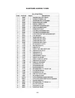
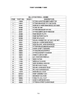
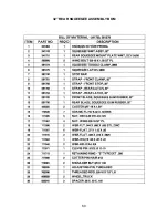
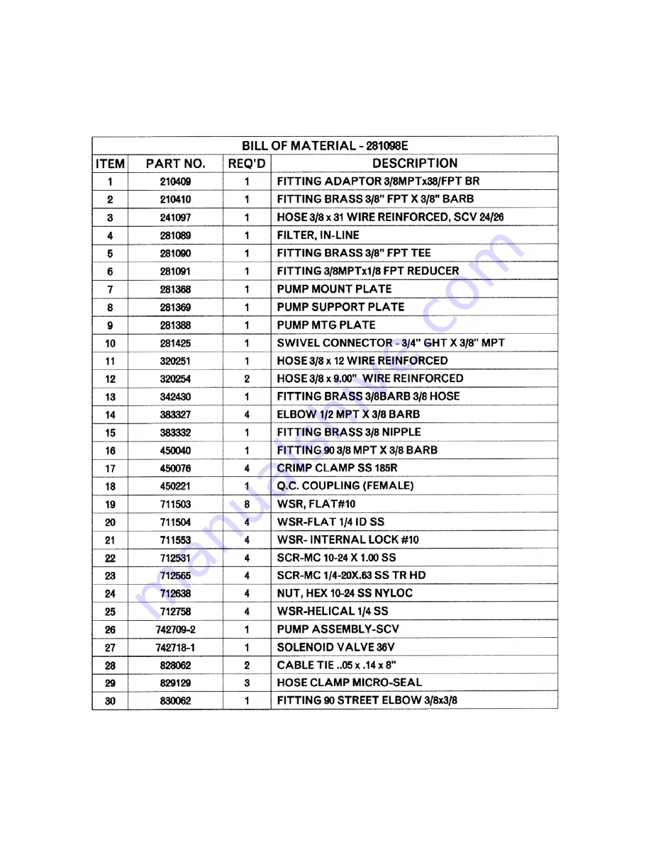
PUMP ASSEMBLY BOM 


Summary of Contents for SCV 28/32

Page 1: ...SCV 28 32 RIDER SCRUBBER OPERATION SERVICE PARTS CARE ...

Page 2: ...ufacturers suggested maintenance instructions as provided in this booklet Use original Minuteman supplied parts TECHNICAL SPECIFICATIONS Model SCVTM 28 32 Model No SCV28CQP SCV28DQP SCV32CQP SCV32DQP SCV28C SCV28D SCV32C SCV32D SCV28CPLUS SCV28DPLUS SCV32CPLUS SCV32DPLUS Current 60 Amps Voltage Batteries 36 volts 6 6volt Battery Capacity 275 Ah Optional 395 Ah batteries available Sound Level 75 dB...

Page 3: ...3 ...

Page 4: ... SWITCH 12 OPERATION MODES 13 1 REGULAR SCRUB MODE 13 2 HEAVY SCRUB MODE 13 3 DOUBLE SCRUB MODE 13 4 VACUUM ONLY MODE 14 5 TRANSPORT MODE 14 6 SOLUTION CONTROL KNOB 14 7 BATTERY GAUGE 14 FAULT DIAGNOSTIC CODES 15 FAULT DIAGNOSTIC CODES DECAL 15 EMPTY SOLUTION TANK INDICATOR 16 LOW BATTERY INDICATOR 16 POWER SAVE MODE 16 OPERATION OF CONTROLS 17 STEERING WHEEL 17 ACCELERATOR PEDAL 17 SEAT 17 DIRECT...

Page 5: ...BLY II 39 MAINFRAME ASSEMBLY II BOM 40 FRONT DRIVE ASSEMBLY 41 FRONT DRIVE ASSEMBLY BOM 42 STEERING ASSEMBLY 43 STEERING ASSEMBLY BOM 44 SOLUTION TANK ASSEMBLY SEAT ASSEMBLY 45 SOLUTION TANK ASSEMBLY SEAT ASSEMBLY BOM s 46 ELECTRICAL PANEL 47 CONSOLE 48 RECOVERY TANK I 49 RECOVERY TANK I BOM 50 RECOVERY TANK II 51 BATTERY BOX ASSEMBLY 52 PUMP ASSEMBLY 53 PUMP ASSEMBLY BOM 54 REAR AXLE ASSEMBLY 55 ...

Page 6: ...IDE 72 DISK SCRUBDECK SIDE SQUEEGEE LEFT SIDE 73 DISK SCRUBDECK SIDE SQUEEGEE RIGHT SIDE 74 CYLINDRICAL SCRUBDECK AND ROLLER BUMPER MOUNTING 75 SCV28CQP SCV32CQP BOM s 76 DISK SCRUBDECK AND ROLLER BUMPER MOUNTING 77 SCV28DQP SCV32DQP BOM s 78 PLUMBING DIAGRAM 79 WIRING DIAGRAMS 80 TRIO CONNECTIONS 80 P3 TRIO CONNECTIONS 81 P2 TRIO CONNECTIONS 82 WIRE COLORS CODES 83 LIMITED WARRANTY 84 ...

Page 7: ...ust etc Store or park this machine on a level surface only with the key switch in the off position To prevent unauthorized use machine should be stored or parked with the key removed This machine is designed for level operation only Do not operate on ramps or inclines This machine is not suitable for picking up hazardous dusts Use caution when moving this machine into areas that are below freezing...

Page 8: ...ng Amp Hour capacities Any alternate battery sets can be used if they are of equal physical size and capacity See Battery Compartment for service and installation OPERATOR RESPONSIBILITY Read this manual carefully before operating this machine The operator is responsible for taking care of the daily maintenance and check ups of the machine to keep it in good working condition The operator must inf...

Page 9: ...egee Accelerator Pedal Steering Tilt Lever Steering Wheel Operator s Seat Recovery Tank Lid Recovery Tank Control Console J K L M N O P Q R Directional Switch Safety Latch Battery Compartment Solution Tank Electrical Panel Rear Squeegee Real Wheel Scrubdeck Roller Bumper ...

Page 10: ...Rear Wheel Side Squeegee Accelerator Pedal Solution Tank Steering Tilt Lever Steering Wheel Recovery Tank Lid I J K L M N O P Vacuum Filter Access Vac Inlet Assembly Recovery Tank Battery Compartment Clean Out Cap Recovery Drain Hose Recovery Hose Scrubdeck ...

Page 11: ...11 OPERATOR COMPARTMENT A B C D E Operator s Seat Solution Tank Lid Cup Holder Solution Tank Accelerator Pedal F G H I Steering Wheel Directional Switch Control Panel Safety Latch ...

Page 12: ...ashing to inform the operator that the machine is almost out of power Once this signal is displayed all functions will shut off including transport mode The operator must then turn the key switch OFF and then ON to reset the machine The machine will then have only a few minutes left of reserve power to briefly use Vacuum Only mode to pick up any remaining solution on the floor and Transport mode t...

Page 13: ...operate the same was as if it was in Regular Scrub Mode only this mode applies more solution and brush pressure is increased This mode is used for high traffic areas and areas that have been heavily soiled but do not require time for the solution to soak 3 DOUBLE SCRUB MODE When the machine is running in this mode the machine will perform all operations except dirty solution recovery This mode can...

Page 14: ...tions of the machine will operate This mode is only used to transport the machine from one location to another at a faster rate of speed 6 SOLUTION CONTROL KNOB This control will adjust the amount of solution that is being dispersed to the floor while in one of the scrub modes Adjust the control clockwise to increase the amount of solution being dispersed The amount of solution applied is variable...

Page 15: ...hen an error or fault occurs within the machine a fault code will appear on the battery gauge represented by a specific number of flashing LEDs The figure below shows a listing of the different codes FAULT DIAGNOSTIC CODES DECAL ...

Page 16: ...ator must then turn the key switch OFF and then ON to reset the machine The machine will then have only a few minutes left of reserve power to briefly use Vacuum Only mode to pick up any remaining solution on the floor and Transport mode to return to the charging station POWER SAVE MODE The SCV is equipped with a power save feature to conserve battery power If the key switch power is left ON and n...

Page 17: ...accelerator pedal is also linked to the machine s dynamic braking system During operation when the accelerator pedal is released the dynamic braking system will automatically halt the movement of the machine without need for an additional brake pedal SEAT The ergonomically designed seat is located on top of the solution tank There is a lever under the seat that allows the operator to adjust the se...

Page 18: ... key switch off a few seconds and then on again The 100 amp circuit breaker can also be used as a main power disconnect this should be used only in case of emergency When tripped the breaker removes power from the main controller and all auxiliary power circuits BATTERY COMPARTMENT The battery compartment is located on the rear of the machine under the recovery tank Unlatching the two safety latch...

Page 19: ...19 BATTERY CONNECTION DIAGRAM BATTERIES INSTALLED WITH SPACERS ...

Page 20: ...olution to the floor and channeled to the rear of the machine The disc brushes are also easily removed and installed by easily removing the side deck covers and releasing the quick release clamp Another nice feature that these scrub decks have is the ability to have uniform brush pressure applied to the floor at all times Since the scrub deck brush pressure is computer controlled it will automatic...

Page 21: ... Side Deck Cover 2 Brush Motor Mounting Plate Solution Feed Hose Power Connector Three Sided Knob 4 H I J K L M Bolt 4 Helical Lock Washer 4 Flat Washer 4 Wing Nut for Squeegee Adj 4 Helical Lock Washer for Squeegee Adj 4 Flat Washer for Squeegee Adj 4 ...

Page 22: ...tch to the ON position and select the transport mode with mode selector knob 3 Slide the scrub deck assembly underneath the machine follow instructions as described above 4 Position the scrub deck to align the mounting brackets with the mounting lugs on the lift linkage 5 Lower the lift linkage to the floor by pressing the manual override switch for five seconds see figure 6 Lower the lift linkage...

Page 23: ...the Disk Scrub Deck the wire is disconnected When using the Cylindrical Scrub Deck the wire is connected to the terminal block located in the electrical box beneath the TRIO Controller This terminal block is divided into five sections each separated by a divider The four leftmost sections contain one column each of spade terminals The section on the right contains two columns of spade terminals th...

Page 24: ...r Cylindrical Scrub Deck Lower the scrub deck by switching to a scrubbing mode and when the brushes start up turn off the key switch At this point the side squeegees should be resting vertically no deflection on the floor Press down on the side squeegee bracket assembly from each end while making sure that the blade is uniformly deflected in a 45 degree angle along its whole length Tighten the win...

Page 25: ...nge the brushes without having to realign the side squeegees This is accomplished by removing the yellow three sided knob Item C and swinging the squeegee along the hinge bracket Item D located at the front of the deck gaining access to the brushes Once completed inserting new brushes replace the brush doors and swing the squeegee back into place tightening down the knob Item C In order to remove ...

Page 26: ...or specific applications Each blade configuration has two usable edges The rear blade however has four usable edges The squeegee is pre adjusted at the factory Adjustments may be required to get optimum performance for different floors and conditions REAR SQUEEGEE COMPONENTS A B C D E F G H Rear Squeegee Blade Wing Nut 2 Caster Stem 2 Swivel Caster 2 Wing Jam Nut 2 Turnbuckle Adjustment Knob Front...

Page 27: ...ade Adjust the casters and retighten the wing jam nuts to lock the caster setting in place 7 Pitch adjustment is necessary if the outer ends on the squeegee blade do not contact the floor and there is too much deflection in the middle area or if the outer ends are over deflected and there is no contact in the middle 8 To adjust the pitch Repeat step 2 9 Loosen the two wing jam nuts item E that loc...

Page 28: ...y Do not lay tools or metal objects on top of the batteries Charging batteries generate explosive gasses DO NOT CHARGE BATTERIES WHEN OPEN FLAMES OR SPARKS ARE PRESENT DO NOT SMOKE Make sure the charger is turned off before disconnecting it from the batteries Charge the batteries in a well ventilated area Fluid levels should be checked before and after charging and maintained at the proper levels ...

Page 29: ... your speed brush pressure and solution flow according to the condition of the floor CAUTION To avoid any damage to the floor keep the machine moving when the brushes are turned on 8 When scrubbing check behind the machine occasionally to see that all the dirty water is being picked up If streaking occurs your Recovery Tank may be full the Squeegee hose may be clogged or the Rear Squeegee may requ...

Page 30: ...set the machine The machine will then have only a few minutes left of reserve power to briefly use Vacuum Only mode to pick up any remaining solution on the floor and Transport mode to return to the charging station AFTER USE 1 When finished scrubbing select the Transport mode all functions will shut off brush will turn off and the scrub deck will raise up water flow will cease the rear squeegee w...

Page 31: ...s The brush motor carbon brushes should be checked every 500 hours or once a year NOTE Refer to the Service Manual for more detail on maintenance and service repairs LUBRICATING THE MACHINE Regularly scheduled lubrication of certain machine parts should be performed to insure trouble free operation of the machine Apply a generous amount of grease into the fittings on the machine until grease seeps...

Page 32: ...eplace brushes Wrong brush or cleaning chemical Consult Minuteman Debris caught on scrub brushes Remove debris Moving machine too fast Slow down Poor scrubbing performance Low battery charge Recharge batteries Solution tank empty Fill solution tank Recovery tank full Empty recovery tank Solution lines valves filter or spray jets clogged Flush lines and clean solution filter and spray jets Inadequa...

Page 33: ...k Empty recovery tank Use less or change chemical Use defoaming agent Vacuum motor does not turn on Five LEDs flashing on Battery Gauge Check for motor overload Reset machine Turn key switch off and restart Debris box full Empty and clean debris box Brushes worn Replace brushes Poor sweeping performance Cylindrical System Bristles have taken a set Rotate brushes Solution tank empty Refill solution...

Page 34: ...34 EXPLODED VIEWS MAIN ASSEMBLY I ...

Page 35: ...35 MAIN ASSEMBLY I BOM ...

Page 36: ...36 MAIN ASSEMBLY II ...

Page 37: ...37 MAIN ASSEMBLY II BOM ...

Page 38: ...38 MAINFRAME ASSEMBLY I ...

Page 39: ...39 MAINFRAME ASSEMBLY II ...

Page 40: ...40 MAINFRAME ASSEMBLY II BOM ...

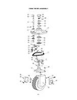
Page 41: ...41 FRONT DRIVE ASSEMBLY ...

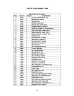
Page 42: ...42 FRONT DRIVE ASSEMBLY BOM ...

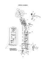
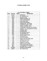
Page 43: ...43 STEERING ASSEMBLY ...

Page 44: ...44 STEERING ASSEMBLY BOM ...

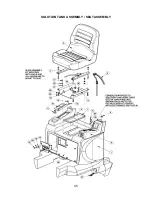
Page 45: ...45 SOLUTION TANK ASSEMBLY SEAT ASSEMBLY ...

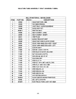
Page 46: ...46 SOLUTION TANK ASSEMBLY SEAT ASSEMBLY BOM s ...

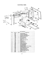
Page 47: ...47 ELECTRICAL PANEL ...

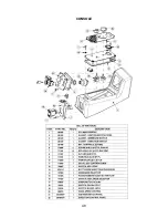
Page 48: ...48 CONSOLE ...

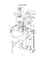
Page 49: ...49 RECOVERY TANK I ...

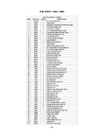
Page 50: ...50 RECOVERY TANK I BOM ...

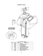
Page 51: ...51 RECOVERY TANK II ...

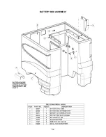
Page 52: ...52 BATTERY BOX ASSEMBLY ...

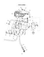
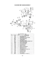
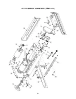
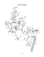
Page 53: ...53 PUMP ASSEMBLY ...

Page 54: ...54 PUMP ASSEMBLY BOM ...

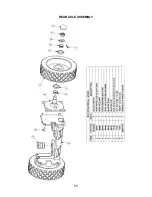
Page 55: ...55 REAR AXLE ASSEMBLY ...

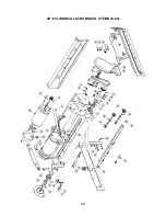
Page 56: ...56 SQUEEGEE MECHANISM ASSEMBLY ...

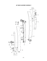
Page 57: ...57 28 REAR SQUEEGEE ASSEMBLY ...

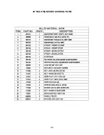
Page 58: ...58 28 REAR SQUEEGEE ASSEMBLY BOM ...

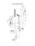
Page 59: ...59 32 REAR SQUEEGEE ASSEMBLY ...

Page 60: ...60 32 REAR SQUEEGEE ASSEMBLY BOM ...

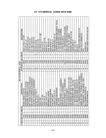
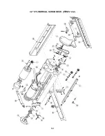
Page 61: ...61 28 CYLINDRICAL SCRUBDECK ITEMS 1 32 ...

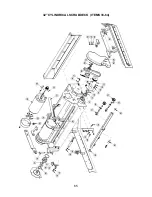
Page 62: ...62 28 CYLINDRICAL SCRUBDECK ITEMS 33 64 ...

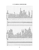
Page 63: ...63 28 CYLINDRICAL SCRUBDECK BOM ...

Page 64: ...64 32 CYLINDRICAL SCRUBDECK ITEMS 1 32 ...

Page 65: ...65 32 CYLINDRICAL SCRUBDECK ITEMS 33 64 ...

Page 66: ...66 32 CYLINDRICAL SCRUBDECK BOM ...

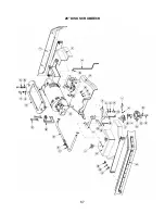
Page 67: ...67 28 DISK SCRUBDECK ...

Page 68: ...68 28 DISK SCRUBDECK BOM ...

Page 69: ...69 32 DISK SCRUBDECK ...

Page 70: ...70 32 DISK SCRUBDECK BOM ...

Page 71: ...71 CYLINDRICAL SCRUBDECK SIDE SQUEEGEE LEFT SIDE ...

Page 72: ...72 CYLINDRICAL SCRUBDECK SIDE SQUEEGEE RIGHT SIDE ...

Page 73: ...73 DISK SCRUBDECK SIDE SQUEEGEE LEFT SIDE ...

Page 74: ...74 DISK SCRUBDECK SIDE SQUEEGEE RIGHT SIDE ...

Page 75: ...75 CYLINDRICAL SCRUBDECK AND ROLLER BUMPER MOUNTING ...

Page 76: ...76 SCV28CQP SCV32CQP BOM s ...

Page 77: ...77 DISK SCRUBDECK AND ROLLER BUMPER MOUNTING ...

Page 78: ...78 SCV28DQP SCV32DQP BOM s ...

Page 79: ...79 PLUMBING DIAGRAM ...

Page 80: ...80 WIRING DIAGRAMS TRIO CONNECTIONS ...

Page 81: ...81 P3 TRIO CONNECTIONS ...

Page 82: ...82 P2 TRIO CONNECTIONS ...

Page 83: ...83 WIRE COLORS CODES ...

Page 84: ...e the sole property of Minuteman International Inc or its original manufacturer whichever the case may be Minuteman International Inc disclaims any implied warranty including the warranty of merchantability and the warranty of fitness for a particular purpose Minuteman International Inc assumes no responsibility for any special incidental or consequential damages This limited warranty is applicabl...

Reviews: