SIDE SQUEEGEE
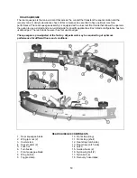
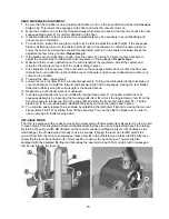
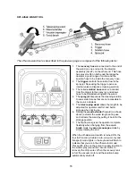
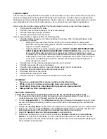
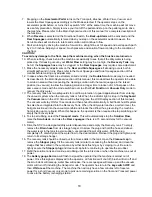
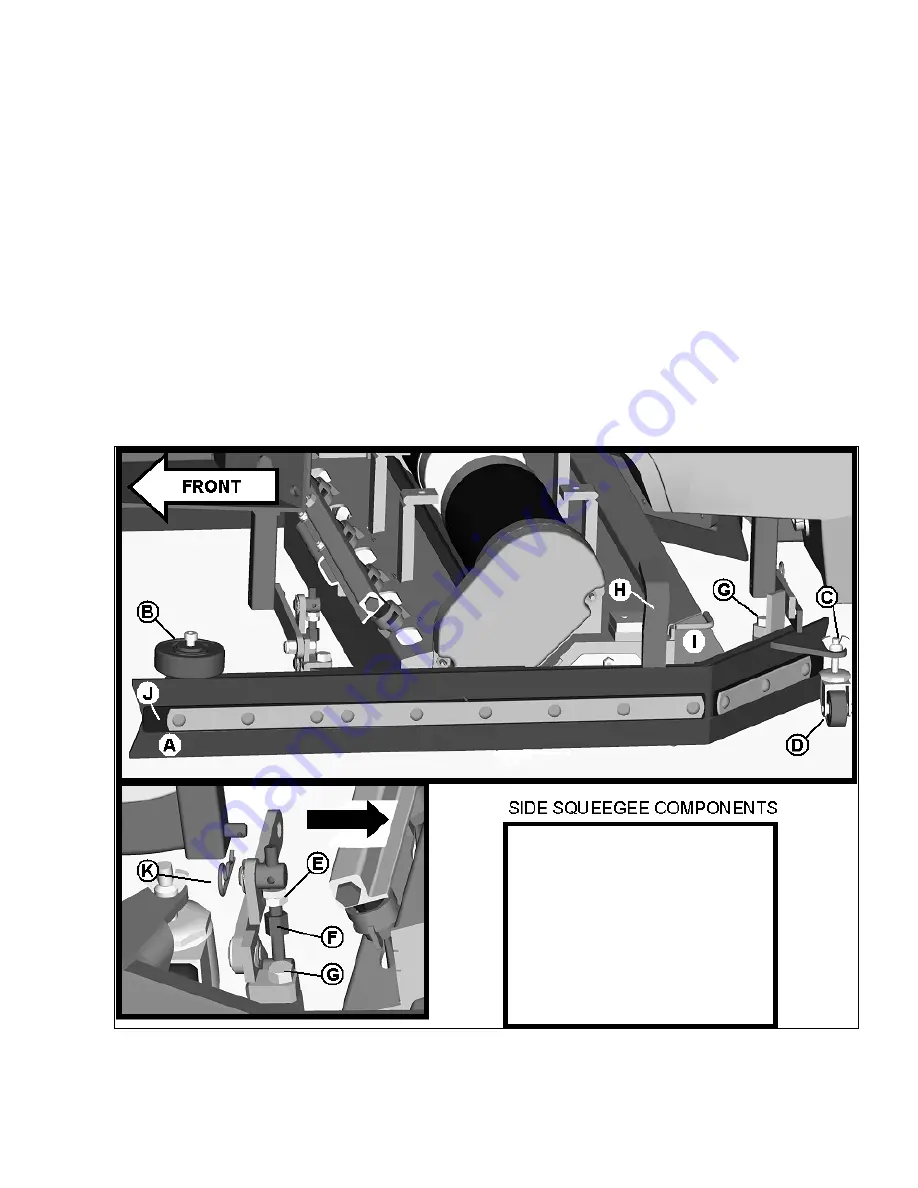
The side squeegees (left and right) are attached to the machine mainframe. These items channel the dirty
solution to the rear squeegee, helping contain the water within the machine’s cleaning path. These
squeegees are raised when the scrub deck is in the raised position. When the scrub deck is deployed, the
side squeegees are also lowered. A lift bracket (item
H
) raises the side squeegee off the floor when the
machine is in a non-scrubbing mode. The side squeegees are equipped with an adjustable caster (item
D
)
to control the blade deflection (lowering the caster lessens blade deflection). To adjust the deflection,
loosen the wing jam nut (item
C
) and turn the caster stem as described below. If the squeegee blade is
deflecting too much, the casters need to be lowered to control the down pressure. Lower the caster by
turning the exposed threaded stem on the caster clockwise. Make the adjustment a few turns at a time. If
the blades are not deflecting enough, raise the caster by turning the stem counter-clockwise to adjust the
caster height to allow more down pressure on the squeegee. A nylon shear bolt (item
G
) located at the front
and rear of the squeegee prevents undue damage to the assembly in case it hits a solid object. If the side
squeegee is subjected to high impact, the bolt will shear off and prevent severe damage to the assembly. A
turnbuckle adjustment (item
F
) is provided to adjust the pitch for optimum wiping performance. To adjust,
loosen Lock nut (item
E
) and turn the turnbuckle to make the necessary adjustments. To clean out the
debris box (item
I
), set the machine to the double scrub mode and when the scrub deck is lowered to the
floor, turn the key switch off. Slightly lift the debris box up by its handles and slide out towards you.
A. Squeegee
blade
B. Roller guide wheel
C. Wing jam nut
D. Swivel caster
E. Lock nut (2)
F. Turnbuckle
G. Shear bolt (2)
H. Lift bracket
I. Debris box
J. Backer strip
K. Cotter pin
13
Summary of Contents for SCV28
Page 1: ...SCV 28 32 RIDER SCRUBBER OPERATION SERVICE PARTS CARE ...
Page 3: ...3 ...
Page 31: ...EXPLODED VIEWS MAIN ASSEMBLY I 25 ...
Page 32: ...26 ...
Page 33: ...MAIN ASSEMBLY II 27 ...
Page 34: ...28 ...
Page 35: ...MAINFRAME ASSEMBLY I 29 ...
Page 36: ...MAINFRAME ASSEMBLY II 30 ...
Page 37: ...31 ...
Page 38: ...FRONT DRIVE ASSEMBLY 32 ...
Page 39: ...33 ...
Page 40: ...STEERING ASSEMBLY 34 ...
Page 41: ...35 ...
Page 42: ...LCD HOUSING ASSEMBLY 36 ...
Page 43: ...SOLUTION TANK ASSEMBLY 37 ...
Page 44: ...38 ...
Page 45: ...ELECTRICAL PANEL ASSEMBLY 39 ...
Page 46: ...CONSOLE ASSEMBLY 40 ...
Page 47: ...RECOVERY TANK ASSEMBLY I 41 ...
Page 48: ...42 ...
Page 49: ...RECOVERY TANK II 43 ...
Page 50: ...DIVERTER ASSEMBLY 44 ...
Page 51: ...BATTERY BOX ASSEMBLY 45 ...
Page 52: ...PUMP ASSEMBLY 46 ...
Page 53: ...47 ...
Page 54: ...REAR AXLE ASSEMBLY 48 ...
Page 55: ...SQUEEGEE MECHANISM ASSEMBLY 49 ...
Page 56: ...REAR SQUEEGEE ASSEMBLY 28 50 ...
Page 57: ...51 ...
Page 58: ...REAR SQUEEGEE ASSEMBLY 32 52 ...
Page 59: ...53 ...
Page 60: ...28 CYLINDRICAL SCRUB DECK ASSEMBLY 54 ...
Page 61: ...55 ...
Page 62: ...28 DISC SCRUB DECK ASSEMBLY 56 ...
Page 63: ...57 ...
Page 64: ...32 CYLINDRICAL SCRUB DECK ASSEMBLY 58 ...
Page 65: ...59 ...
Page 66: ...32 DISC SCRUB DECK ASSEMBLY 60 ...
Page 67: ...61 ...
Page 68: ...CYLINDRICAL DECK AND SIDE SQUEEGEE MOUNTING 62 ...
Page 69: ...63 ...
Page 70: ...DISC SCRUBDECK AND SIDE SQUEEGEE MOUNTING 64 ...
Page 71: ...65 ...
Page 72: ...28 SIDE SQUEEGEE RIGHT SIDE 66 ...
Page 73: ...28 SIDE SQUEEGEE LEFT SIDE 67 ...
Page 74: ...32 SIDE SQUEEGEE RIGHT SIDE 68 ...
Page 75: ...32 SIDE SQUEEGEE LEFT SIDE 69 ...
Page 76: ...OFF AISLE WAND ASSEMBLY 70 ...
Page 77: ...71 ...
Page 78: ...PLUMBING DIAGRAM 72 ...
Page 79: ...WIRING DIAGRAMS POWER WIRING 73 ...
Page 80: ...INPUTS TO CONTROLLER 74 ...
Page 81: ...OUTPUTS FROM CONTROLLER 75 ...
Page 82: ...KEYBOARD WIRING 76 ...
Page 83: ...MACHINE SCHEMATIC 77 ...
Page 84: ...1 03 78 ...

