background image


 26

Summary of Contents for SCV28

Page 1: ...SCV 28 32 RIDER SCRUBBER OPERATION SERVICE PARTS CARE ...

Page 2: ...Follow the manufacturers suggested maintenance instructions as provided in this booklet Use original Minuteman supplied parts TECHNICAL SPECIFICATIONS Model SCVTM 28 32 Model No SC280000QP SC280001QP SC32000QP SC320001QP SC280000CE SC280001CE SC320000CE SC320001CE Current 65 Amps Voltage Batteries 36 volts 6 6volt Battery Capacity 370 AH Sound Level 72 dB Dimensions LxWxH 64 x 31 x 54 160cm x 78 7...

Page 3: ...3 ...

Page 4: ...DJUSTMENT 6 EMPTY SOLUTION TANK INDICATOR 6 RECOVERY TANK FULL INDICATOR 6 LOW BATTERY INDICATOR 7 DIAGNOSTIC CODE 7 FAULT DIAGNOSTIC CODE 7 OPERATION OF CONTROLS 8 POWER SAVE MODE 8 ACCELERATOR PEDAL 8 SEAT 8 STEERING WHEEL 8 MECHANICAL PARKING BRAKE 9 EMERGENCY DISCONNECT BUTTON 9 CIRCUIT BREAKERS 9 BATTERY COMPARTMENT 10 SCRUB DECK 11 CYLINDRICAL 11 SCRUB DECK 11 DISC SCRUB DECK 11 SCRUB DECK I...

Page 5: ... ASSEMBLY 60 CYLINDRICAL DECK AND SIDE SQUEEGEE MOUNTING 62 DISC SCRUBDECK AND SIDE SQUEEGEE MOUNTING 64 28 SIDE SQUEEGEE RIGHT SIDE 66 28 SIDE SQUEEGEE LEFT SIDE 67 32 SIDE SQUEEGEE RIGHT SIDE 68 32 SIDE SQUEEGEE LEFT SIDE 69 OFF AISLE WAND ASSEMBLY 70 PLUMBING DIAGRAM 72 WIRING DIAGRAMS 73 INPUTS TO CONTROLLER 74 OUTPUTS FROM CONTROLLER 75 KEYBOARD WIRING 76 MACHINE SCHEMATIC 77 2 ...

Page 6: ...in dust etc Store or park this machine on a level surface only with parking brake engaged To prevent unauthorized use machine should be stored or parked with the key removed This machine is designed for level operation only Do not operate on ramps or inclines This machine is not suitable for picking up hazardous dusts Use caution when moving this machine into areas that are below freezing temperat...

Page 7: ...s manual carefully before operating this machine The operator is responsible in taking care of the daily maintenance and check ups of the machine to keep it in good working condition The operator must inform the service mechanic or supervisor when the scheduled maintenance intervals are required as stated in the MAINTENANCE section of this manual Before starting familiarize yourself with the machi...

Page 8: ...ank lid Vacuum filter access Vacuum diverter Off aisle wand Recovery tank Battery compartment Clean out cap Recovery dump hose Safety latch Recovery hose Scrub deck MACHINE COMPONENTS DRIVER S COMPARTMENT A B C D E F G H I J K L Operator s seat Solution tank lid Cup holder Solution tank Tilt wheel lever Accelerator pedal Parking brake LCD display panel Steering wheel Directional switch Control con...

Page 9: ...rational settings are retained even when the power is turned off and on This also serves as a reset switch when error or fault codes appear on the LCD screen Off aisle wand switch B On Off control for the water supply to the wand and vacuum motor Headlight switch C On Off control for the headlights Main Keyboard D The main keyboard is divided into three sections Machine settings Machine modes and ...

Page 10: ...ution to stay on the floor emulsifying the grease and oil If the operator stops moving in either direction the machine will automatically raise and turn off the brushes After double scrubbing the operator should use the vacuum only mode to recover the dirty solution water from the floor See the LCD display section in this book to see the image on the screen looks like when this button is selected ...

Page 11: ...ON TANK INDICATOR The light inside this icon will be illuminated when the solution tank is empty At the same instant the LCD display will have a flashing bar on the solution flow icon signaling the operator of the solution tank status and the solution pump shuts off See the LCD display section in this book to see the image on the screen looks like when this button is selected RECOVERY TANK FULL IN...

Page 12: ...lhouette of the machine will be displayed and arrow pointing to a direction as selected on the directional switch BRUSH PRESSURE ADJUSTMENT Increasing pressure adds more bars to the scale decreasing pressure removes bars from the scale WATER FLOW ADJUSTMENT Increasing flow adds more bars to scale decreasing flow removes bars from scale EMPTY SOLUTION TANK INDICATOR A flashing bar across the water ...

Page 13: ...is condition The operator has to turn the key switch OFF and then ON to reset the machine If this does not work servicing the machine may be necessary Below is a list of fault and diagnostic codes for troubleshooting See Troubleshooting tips section for further details SCV Fault Codes Switch Reference Codes May indicate incorrectly wired input switches 07xx Throttle Codes May indicate incorrectly ...

Page 14: ...tch making machine propulsion not possible without the operator sitting on the seat SEAT The ergonomically designed seat is located on top of the solution tank There is a lever under the seat that allows the operator to adjust the seat forward or backward for operator comfort There is an interlock switch located inside the seat This makes it impossible to engage the traction drive circuitry withou...

Page 15: ...ted from moving The mechanical parking brake system is self cleaning and periodic use is recommended to avoid build up of foreign matter that may cause seizing in the mechanism and rust build up EMERGENCY DISCONNECT BUTTON This button is located in the middle of the electrical panel that is directly underneath the operator s seat When the red emergency button is pressed power will be turned off Us...

Page 16: ...enables the operator to tilt the recovery tank and access the batteries for servicing and maintenance make sure recovery tank has been drained before tilting The battery compartment contains six 6 volt batteries connected in series Connect the batteries according to the battery connection diagram see diagram The recommended batteries are 370Ah Minuteman P N 956715 10 ...

Page 17: ...he machine The disc brushes are also easily removed and installed with the quick release clamp by using any of the three access doors Another nice feature that these scrub decks have is the ability to have uniform brush pressure applied to the floor at all times Since the scrub deck brush pressure is computer controlled it will automatically adjust and compensate to uneven contours on the floor wh...

Page 18: ...ructions as described above 6 Position the scrub deck to align the mounting brackets with the mounting lugs on the lift linkage 7 Lower the lift linkage to the floor by pressing the increase brush pressure button for ten seconds Pressing the up and down brush pressure button for ten seconds toggles the scrub deck control into a manual up and down mode for the scrub deck linkage 8 Lower the lift li...

Page 19: ...he caster clockwise Make the adjustment a few turns at a time If the blades are not deflecting enough raise the caster by turning the stem counter clockwise to adjust the caster height to allow more down pressure on the squeegee A nylon shear bolt item G located at the front and rear of the squeegee prevents undue damage to the assembly in case it hits a solid object If the side squeegee is subjec...

Page 20: ...lications Each blade configuration has two usable edges The rear blade however has four usable edges The squeegee is pre adjusted at the factory Adjustments may be required to get optimum performance for different floors and conditions REAR SQUEEGEE COMPONENTS 1 Rear squeegee blade 2 Wing jam nut 2 3 Caster stem 4 Swivel caster 2 5 Lock nut 6 Turnbuckle 7 Front squeegee blade 8 Wing bolt 2 9 Toggl...

Page 21: ... the turnbuckle assembly Turning the turnbuckle item 6 clockwise or counter clockwise controls the forward and backward pitch of the squeegee Having the rear blades deflected uniformly along its entire length is the desired set up 10 Repeat step 2 until desired set up is achieved 11 In certain applications where a non slotted front wiper blade item 7 is needed detach the rear squeegee assembly by ...

Page 22: ...ak soiled areas that are not accessible to the main scrub deck 5 The telescoping wand allows the length to be adjusted for operator comfort and better storage when not in use 6 Sliding the wand extender forward as shown above extends the wand length during use and retracts the wand by pulling it back for the storage position 7 The flip flop tool gives the operator complete flexibility when changin...

Page 23: ...ge once a week Check for wire string or twine wrapped around the scrub brushes Check the squeegees for wear and damage Check the rear squeegee suction hose and off aisle wand hose for obstructions Empty and clean the debris box cylindrical systems only Drain and clean the recovery tank Check under the machine for leaks Check the service records to determine maintenance requirements WARNING Be sure...

Page 24: ...from entering the vacuum system when the recovery tank is full When the indicator light is lit up in the Keyboard the Vacuum icon in the LCD Screen will be flashing see the LCD Display section of this manual The vacuum will stay ON for 15 seconds and then shut off automatically A ball float shut off system has also been integrated into the Recovery Tank When the dirty water reaches a certain level...

Page 25: ...mbing 3 Empty the recovery tank as described on line 15 and 16 4 Remove the brushes or pad holders and rinse them in warm water and hang to dry 5 Remove the rear squeegee rinse with warm water and reinstall after cleaning 6 Remove the side squeegees rinse with warm water and remove the debris box cylindrical system only and clean thoroughly The debris box can be removed from either side of the mac...

Page 26: ...he brush motor carbon brushes should be checked every 500 hours or once a year NOTE Refer to the Service Manual for more detail on maintenance and service repairs LUBRICATING THE MACHINE Regularly scheduled lubrication of certain machine parts should be performed to insure trouble free operation of the machine Apply a generous amount of grease into the fittings on the machine until grease seeps ou...

Page 27: ...e Broken brush drive belts on cylindrical system replace belt s Check power connection Reconnect plugs Reset machine Turn key switch off and restart Solution tank empty Fill solution tank Recovery tank full Empty recovery tank Solution lines valves filter or spray jets clogged Flush lines and clean solution filter and spray jets Inadequate solution flow or no solution to the floor Solution solenoi...

Page 28: ...itch off and restart Debris box full Empty and clean debris box Brushes worn Replace brushes Poor sweeping performance Cylindrical System Bristles have taken a set Rotate brushes Solution tank empty Refill solution tank Solution tank empty indicator light on Faulty float switch Replace float switch Recovery tank full Empty recovery tank Float switch full of debris Clean float switch Recovery tank ...

Page 29: ...ns on the SCV and LCD 7600 Brush motor disconnected error Open circuit on brush motors or brush motor wiring Check the brush motor connection on the SCV and check the wiring from this connector down to the brush motor and checking connections all the way Otherwise possible brush motor fault 7601 Brush current foldback Brush current overload thermal trip Incorrect programming incorrectly specified ...

Page 30: ...ring to the emergency stop switch and the emergency stop switch itself Otherwise incorrect operation of machine 2C00 Low battery error Low voltage warning Recharge batteries immediately 2F01 Potentiometer displace error Throttle in drive position during switch on Incorrect operation of machine Otherwise check the mechanical condition of the throttle mechanism Otherwise check for wiring short circu...

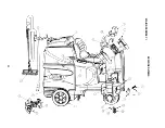
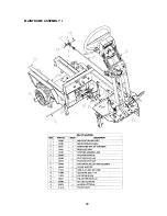
Page 31: ...EXPLODED VIEWS MAIN ASSEMBLY I 25 ...
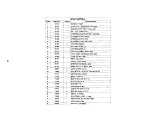
Page 32: ...26 ...

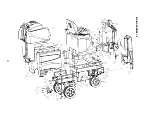
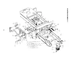
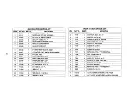
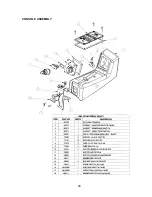
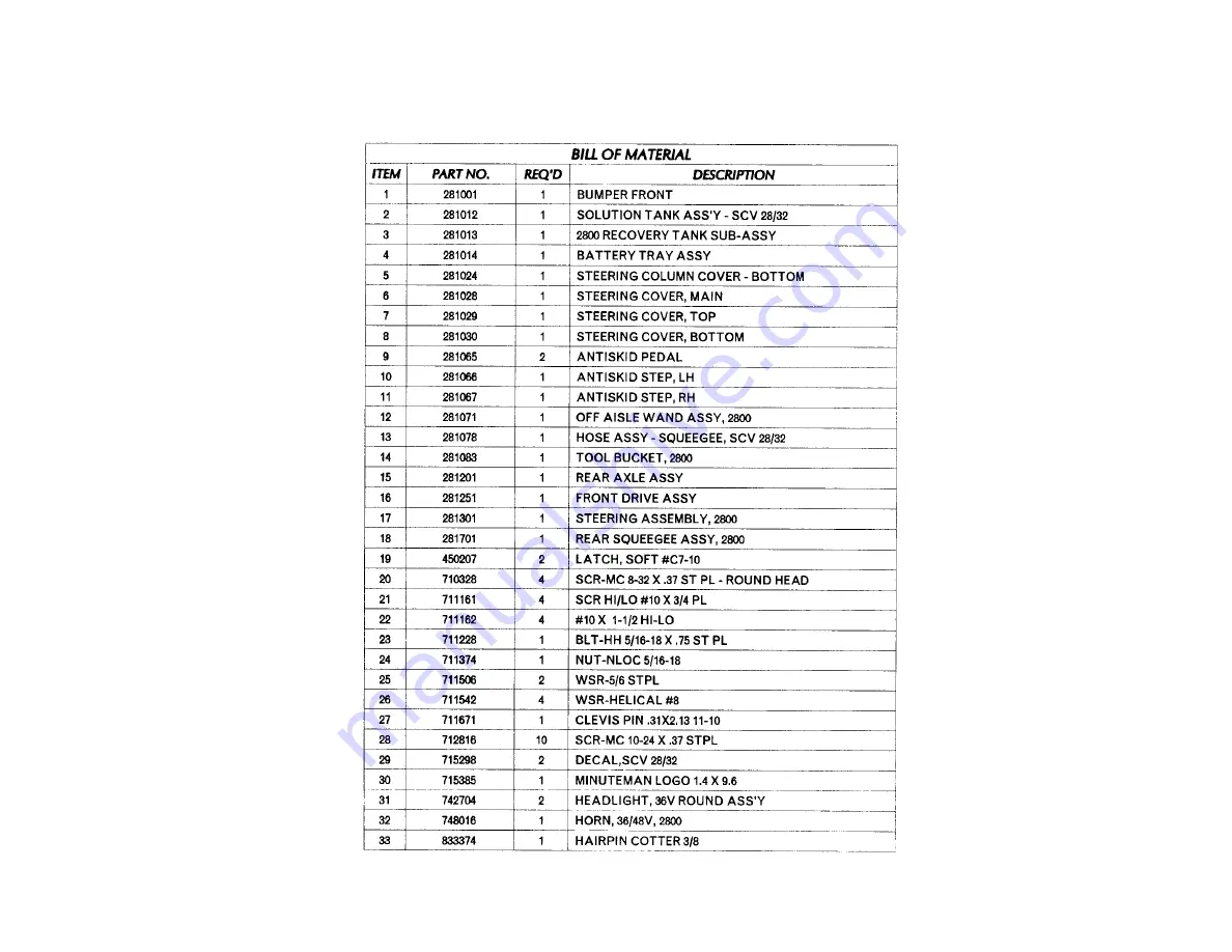
Page 33: ...MAIN ASSEMBLY II 27 ...
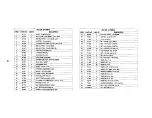
Page 34: ...28 ...

Page 35: ...MAINFRAME ASSEMBLY I 29 ...

Page 36: ...MAINFRAME ASSEMBLY II 30 ...

Page 37: ...31 ...

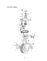
Page 38: ...FRONT DRIVE ASSEMBLY 32 ...

Page 39: ...33 ...

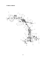
Page 40: ...STEERING ASSEMBLY 34 ...

Page 41: ...35 ...

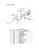
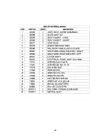
Page 42: ...LCD HOUSING ASSEMBLY 36 ...

Page 43: ...SOLUTION TANK ASSEMBLY 37 ...

Page 44: ...38 ...

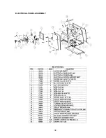
Page 45: ...ELECTRICAL PANEL ASSEMBLY 39 ...

Page 46: ...CONSOLE ASSEMBLY 40 ...

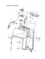
Page 47: ...RECOVERY TANK ASSEMBLY I 41 ...

Page 48: ...42 ...

Page 49: ...RECOVERY TANK II 43 ...

Page 50: ...DIVERTER ASSEMBLY 44 ...

Page 51: ...BATTERY BOX ASSEMBLY 45 ...

Page 52: ...PUMP ASSEMBLY 46 ...

Page 53: ...47 ...

Page 54: ...REAR AXLE ASSEMBLY 48 ...

Page 55: ...SQUEEGEE MECHANISM ASSEMBLY 49 ...

Page 56: ...REAR SQUEEGEE ASSEMBLY 28 50 ...

Page 57: ...51 ...

Page 58: ...REAR SQUEEGEE ASSEMBLY 32 52 ...

Page 59: ...53 ...

Page 60: ...28 CYLINDRICAL SCRUB DECK ASSEMBLY 54 ...

Page 61: ...55 ...

Page 62: ...28 DISC SCRUB DECK ASSEMBLY 56 ...

Page 63: ...57 ...

Page 64: ...32 CYLINDRICAL SCRUB DECK ASSEMBLY 58 ...

Page 65: ...59 ...

Page 66: ...32 DISC SCRUB DECK ASSEMBLY 60 ...

Page 67: ...61 ...

Page 68: ...CYLINDRICAL DECK AND SIDE SQUEEGEE MOUNTING 62 ...

Page 69: ...63 ...

Page 70: ...DISC SCRUBDECK AND SIDE SQUEEGEE MOUNTING 64 ...

Page 71: ...65 ...

Page 72: ...28 SIDE SQUEEGEE RIGHT SIDE 66 ...

Page 73: ...28 SIDE SQUEEGEE LEFT SIDE 67 ...

Page 74: ...32 SIDE SQUEEGEE RIGHT SIDE 68 ...

Page 75: ...32 SIDE SQUEEGEE LEFT SIDE 69 ...

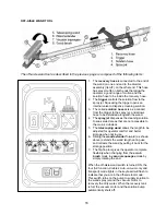
Page 76: ...OFF AISLE WAND ASSEMBLY 70 ...

Page 77: ...71 ...

Page 78: ...PLUMBING DIAGRAM 72 ...

Page 79: ...WIRING DIAGRAMS POWER WIRING 73 ...

Page 80: ...INPUTS TO CONTROLLER 74 ...

Page 81: ...OUTPUTS FROM CONTROLLER 75 ...

Page 82: ...KEYBOARD WIRING 76 ...

Page 83: ...MACHINE SCHEMATIC 77 ...

Page 84: ...1 03 78 ...

Reviews: