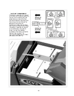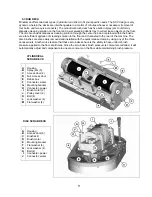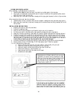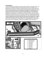
SCRUB DECK INSTALLATION
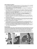
When installing a cylindrical deck to a machine:
1. Install
brushes
after
the deck has been mounted to avoid flat spots on the brushes.
2. Use a piece of cardboard underneath the deck to prevent scratches to the painted surface when
sliding the deck under the machine.
3. Make sure the scrub deck is oriented correctly with the spray jets towards the front of the machine.
When installing a disc scrub deck to a machine:
4. Install brushes on the scrub deck; this aids the installer in sliding the deck assembly into position.
5. Make sure the scrub deck is oriented correctly with the solution hose tee fitting towards the front of
the machine.
INSTALLATION INSTRUCTIONS
1. Park the machine on a flat or level surface.
2. Activate the parking brake.
3. Remove the 2 screws that fasten each plastic side covers on the machine.
4. Turn the key switch to the ON position and select the transport mode on keyboard.
5. Slide the scrub deck assembly underneath the machine (follow instructions as described above)
6. Position the scrub deck to align the mounting brackets with the mounting lugs on the lift linkage.
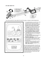
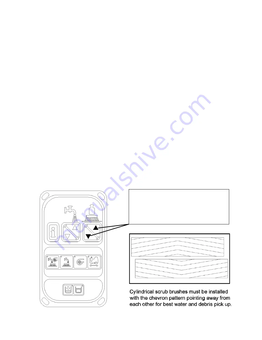
7. Lower the lift linkage to the floor by pressing the increase brush pressure button for ten seconds.
(Pressing the up and down brush pressure button for ten seconds toggles the scrub deck
control into a manual up and down mode for the scrub deck linkage).
8. Lower the lift linkage mounting lugs until they barely touch the scrub deck mounting brackets.
9. Fasten with the four (4) 711242 bolts, 711515 flat washer and 711546 lock washer.
10. For cylindrical scrub deck only:
a. Remove the two access doors (one each end) by removing the (3) nyloc nuts.
b. Install the brushes by sliding through the access opening.
c. Align the notches on the brush with the drive pins on the hub.
d. Push brush all the way until it bottoms out.
e. Insert access door hub to the other end of brush.
f. Reinstall nuts and tighten.
Depressing one of these buttons for ten seconds
will switch you into the manual raise/lower mode.
When you are in this mode, these buttons control
the movement of the lift linkage mechanism. To
get out of this mode, simply reset the machine by
turning the key switch off.
12
Summary of Contents for SCV28
Page 1: ...SCV 28 32 RIDER SCRUBBER OPERATION SERVICE PARTS CARE ...
Page 3: ...3 ...
Page 31: ...EXPLODED VIEWS MAIN ASSEMBLY I 25 ...
Page 32: ...26 ...
Page 33: ...MAIN ASSEMBLY II 27 ...
Page 34: ...28 ...
Page 35: ...MAINFRAME ASSEMBLY I 29 ...
Page 36: ...MAINFRAME ASSEMBLY II 30 ...
Page 37: ...31 ...
Page 38: ...FRONT DRIVE ASSEMBLY 32 ...
Page 39: ...33 ...
Page 40: ...STEERING ASSEMBLY 34 ...
Page 41: ...35 ...
Page 42: ...LCD HOUSING ASSEMBLY 36 ...
Page 43: ...SOLUTION TANK ASSEMBLY 37 ...
Page 44: ...38 ...
Page 45: ...ELECTRICAL PANEL ASSEMBLY 39 ...
Page 46: ...CONSOLE ASSEMBLY 40 ...
Page 47: ...RECOVERY TANK ASSEMBLY I 41 ...
Page 48: ...42 ...
Page 49: ...RECOVERY TANK II 43 ...
Page 50: ...DIVERTER ASSEMBLY 44 ...
Page 51: ...BATTERY BOX ASSEMBLY 45 ...
Page 52: ...PUMP ASSEMBLY 46 ...
Page 53: ...47 ...
Page 54: ...REAR AXLE ASSEMBLY 48 ...
Page 55: ...SQUEEGEE MECHANISM ASSEMBLY 49 ...
Page 56: ...REAR SQUEEGEE ASSEMBLY 28 50 ...
Page 57: ...51 ...
Page 58: ...REAR SQUEEGEE ASSEMBLY 32 52 ...
Page 59: ...53 ...
Page 60: ...28 CYLINDRICAL SCRUB DECK ASSEMBLY 54 ...
Page 61: ...55 ...
Page 62: ...28 DISC SCRUB DECK ASSEMBLY 56 ...
Page 63: ...57 ...
Page 64: ...32 CYLINDRICAL SCRUB DECK ASSEMBLY 58 ...
Page 65: ...59 ...
Page 66: ...32 DISC SCRUB DECK ASSEMBLY 60 ...
Page 67: ...61 ...
Page 68: ...CYLINDRICAL DECK AND SIDE SQUEEGEE MOUNTING 62 ...
Page 69: ...63 ...
Page 70: ...DISC SCRUBDECK AND SIDE SQUEEGEE MOUNTING 64 ...
Page 71: ...65 ...
Page 72: ...28 SIDE SQUEEGEE RIGHT SIDE 66 ...
Page 73: ...28 SIDE SQUEEGEE LEFT SIDE 67 ...
Page 74: ...32 SIDE SQUEEGEE RIGHT SIDE 68 ...
Page 75: ...32 SIDE SQUEEGEE LEFT SIDE 69 ...
Page 76: ...OFF AISLE WAND ASSEMBLY 70 ...
Page 77: ...71 ...
Page 78: ...PLUMBING DIAGRAM 72 ...
Page 79: ...WIRING DIAGRAMS POWER WIRING 73 ...
Page 80: ...INPUTS TO CONTROLLER 74 ...
Page 81: ...OUTPUTS FROM CONTROLLER 75 ...
Page 82: ...KEYBOARD WIRING 76 ...
Page 83: ...MACHINE SCHEMATIC 77 ...
Page 84: ...1 03 78 ...

