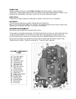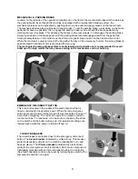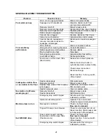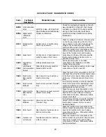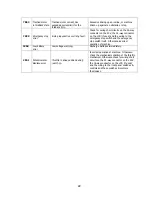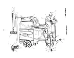
REAR SQUEEGEE ADJUSTMENT
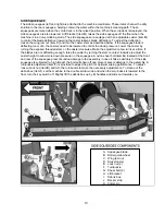
1. Ensure that the scrubber is on a relatively flat surface. Turn on the key switch and select the
Vacuum
only
mode. This lowers the squeegee to the floor and turns the vacuum motor on.
2. Move the scrubber one or two feet forward slowly while someone behind the machine checks the rear
squeegee blade (item
1
) for uniform deflection to the floor.
3. If uneven deflection or lay is evident, minor adjustments may be necessary to avoid streaking and
uneven wear on the blade.
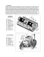
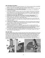
4. To correct this, loosen the wing jam nut (item
2
) in order to adjust the caster height. If the squeegee
blade is deflecting too much, the casters (item
3
) need to be lowered to control the down pressure.
Lower the caster by turning the exposed threaded stem (item
4
) on the caster clockwise. Make the
adjustment a few turns at a time.
Repeat step 2
.
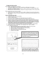
5. If the blades are not deflecting enough, raise the caster by turning the stem counter-clockwise to
adjust the caster height to allow more down pressure on the squeegee.
Repeat step 2.
6. Make sure there is even deflection on the entire length of the rear blade. Adjust the casters and
retighten the wing jam nuts to lock the caster setting in place.
7. Pitch adjustment is necessary if the outer ends on the squeegee blade do not contact the floor and
there is too much deflection in the middle area or if the outer ends are over deflected and there is no
contact in the middle.
8. To adjust the pitch, repeat step 2.
9. Loosen the lock nut (item
5
) in the turnbuckle assembly. Turning the turnbuckle (item
6
) clockwise or
counter-clockwise controls the forward and backward pitch of the squeegee. Having the rear blades
deflected uniformly along its entire length is the desired set-up.
10. Repeat step 2 until desired set-up is achieved.
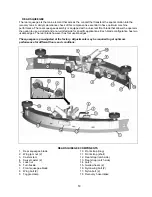
11. In certain applications where a non-slotted front wiper blade (item
7
) is needed, detach the rear
squeegee assembly by loosening the two wing bolts (item
8
). Unlock the toggle clamp (item
9
) on the
front squeegee to release the front long strap (
10
) and slide the front short strap (item
11
). Flip the
blade over to the non-slotted side. Reattach the straps and lock the clamp back in place.
12. You can also easily replace the rear blade by unlatching the latch (item
14
) and removing the two rear
straps (items
12
&
13
) by sliding them off the assembly. You can then flip the blade over in order to
use a new edge for better wiping action.
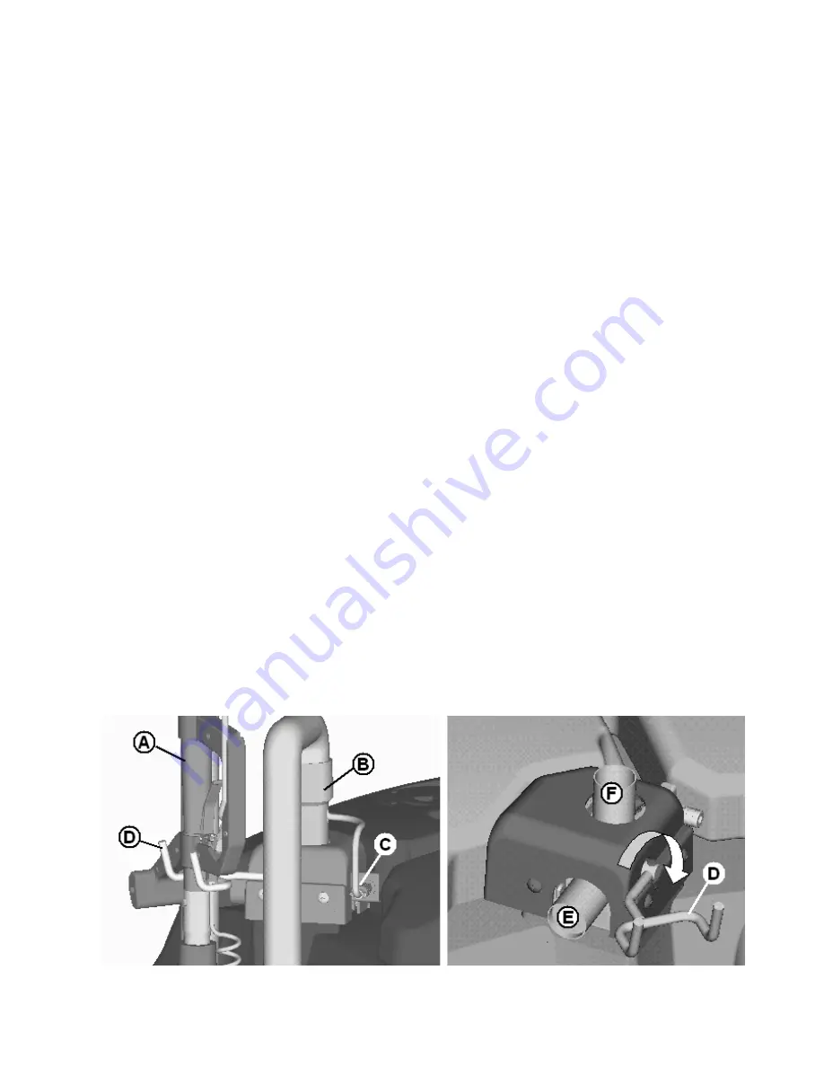
OFF-AISLE WAND
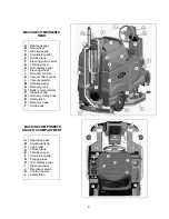
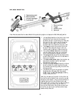
The
SCV
is equipped with a ready-to-use built-in telescoping off-aisle wand (item
A
) system for use in hard
to reach areas. This integrated system eliminates attaching hose for use and detaching hoses for storage.
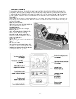
By turning the
pump switch
ON (located on the control console) and flipping a lever that doubles as the
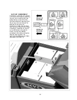
wand hanger, the off-aisle wand is ready to use in seconds. Flipping the lever up (item
D
) diverts the
vacuum flow from the main rear squeegee intake (item
E
) to the off-aisle wand intake (item
F)
.
After use,
simply flip the lever back down to its normal position to use as the hand hanger. The wand is also
equipped with the patented flip-flop tool that allows the operator to switch from scrub brush to squeegee
tool by just rotating the tool end.
15
Summary of Contents for SCV28
Page 1: ...SCV 28 32 RIDER SCRUBBER OPERATION SERVICE PARTS CARE ...
Page 3: ...3 ...
Page 31: ...EXPLODED VIEWS MAIN ASSEMBLY I 25 ...
Page 32: ...26 ...
Page 33: ...MAIN ASSEMBLY II 27 ...
Page 34: ...28 ...
Page 35: ...MAINFRAME ASSEMBLY I 29 ...
Page 36: ...MAINFRAME ASSEMBLY II 30 ...
Page 37: ...31 ...
Page 38: ...FRONT DRIVE ASSEMBLY 32 ...
Page 39: ...33 ...
Page 40: ...STEERING ASSEMBLY 34 ...
Page 41: ...35 ...
Page 42: ...LCD HOUSING ASSEMBLY 36 ...
Page 43: ...SOLUTION TANK ASSEMBLY 37 ...
Page 44: ...38 ...
Page 45: ...ELECTRICAL PANEL ASSEMBLY 39 ...
Page 46: ...CONSOLE ASSEMBLY 40 ...
Page 47: ...RECOVERY TANK ASSEMBLY I 41 ...
Page 48: ...42 ...
Page 49: ...RECOVERY TANK II 43 ...
Page 50: ...DIVERTER ASSEMBLY 44 ...
Page 51: ...BATTERY BOX ASSEMBLY 45 ...
Page 52: ...PUMP ASSEMBLY 46 ...
Page 53: ...47 ...
Page 54: ...REAR AXLE ASSEMBLY 48 ...
Page 55: ...SQUEEGEE MECHANISM ASSEMBLY 49 ...
Page 56: ...REAR SQUEEGEE ASSEMBLY 28 50 ...
Page 57: ...51 ...
Page 58: ...REAR SQUEEGEE ASSEMBLY 32 52 ...
Page 59: ...53 ...
Page 60: ...28 CYLINDRICAL SCRUB DECK ASSEMBLY 54 ...
Page 61: ...55 ...
Page 62: ...28 DISC SCRUB DECK ASSEMBLY 56 ...
Page 63: ...57 ...
Page 64: ...32 CYLINDRICAL SCRUB DECK ASSEMBLY 58 ...
Page 65: ...59 ...
Page 66: ...32 DISC SCRUB DECK ASSEMBLY 60 ...
Page 67: ...61 ...
Page 68: ...CYLINDRICAL DECK AND SIDE SQUEEGEE MOUNTING 62 ...
Page 69: ...63 ...
Page 70: ...DISC SCRUBDECK AND SIDE SQUEEGEE MOUNTING 64 ...
Page 71: ...65 ...
Page 72: ...28 SIDE SQUEEGEE RIGHT SIDE 66 ...
Page 73: ...28 SIDE SQUEEGEE LEFT SIDE 67 ...
Page 74: ...32 SIDE SQUEEGEE RIGHT SIDE 68 ...
Page 75: ...32 SIDE SQUEEGEE LEFT SIDE 69 ...
Page 76: ...OFF AISLE WAND ASSEMBLY 70 ...
Page 77: ...71 ...
Page 78: ...PLUMBING DIAGRAM 72 ...
Page 79: ...WIRING DIAGRAMS POWER WIRING 73 ...
Page 80: ...INPUTS TO CONTROLLER 74 ...
Page 81: ...OUTPUTS FROM CONTROLLER 75 ...
Page 82: ...KEYBOARD WIRING 76 ...
Page 83: ...MACHINE SCHEMATIC 77 ...
Page 84: ...1 03 78 ...

