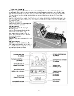
THE SCV RIDER
This machine was designed with total
operator comfort and ease of use in mind. All machine components
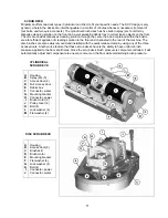
have been designed as a total system to efficiently clean dirty floors. The SCV has four available scrub
head types and sizes to fit specific applications.
Please contact your Minuteman representative for specific
recommendations for the correct scrub head type, size, and brush type and chemical applications.
Before using the machine, always perform the following steps to ensure proper machine operation.
•
Check under the machine for leaks.
•
Check the rear and side squeegees for wear and damage.
•
Check the steering for proper operation.
•
Check the solution and recovery tanks.
After using the machine, always perform the following steps:
•
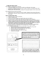
Check the battery charge level. Charge batteries if necessary. When charging batteries, extra
precaution is required:
Battery acid can cause burns. When working on or around batteries, always wear
protective clothing and safety glasses. Remove metal jewelry. Do not lay tools or metal
objects on top of the batteries.
Charging batteries generate explosive gasses.
DO NOT CHARGE BATTERIES WHEN
OPEN FLAMES OR SPARKS ARE PRESENT. DO NOT SMOKE.
Make sure the charger
is turned off before disconnecting it from the batteries. Charge the batteries in a well-
ventilated area. Fluid levels should be checked before and after charging and maintained
at the proper levels. If low, add water until the metal plates are covered. If the machine is
not used for an extended period of time, batteries should be kept fully charged with a
boost charge once a week.
•
Check for wire, string, or twine wrapped around the scrub brushes.
•
Check the squeegees for wear and damage.
•
Check the rear squeegee suction hose and off-aisle wand hose for obstructions.
•
Empty and clean the debris box (cylindrical systems only).
•
Drain and clean the recovery tank.
•
Check under the machine for leaks.
•
Check the service records to determine maintenance requirements.
WARNING!
•
Be sure you understand the machine controls and their functions.
•
While on ramps or inclines, avoid sudden stops when tanks are filled.
•
Avoid abrupt sharp turns. Slow down driving speed when going downhill.
•
Always drive up when cleaning ramps.
MACHINE OPERATION
Follow the instructions in preparing the machine for use as described in this manual.
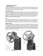
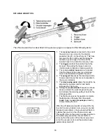
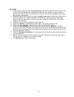
1. While seated on the machine, adjust the steering wheel to desired position (for comfort and
unobstructed view of the LCD panel) using the tilt wheel lever.
2. Turn
the
Key switch ON
(I). The
LCD panel
will light up and display the Minuteman logo for a few
seconds and display the
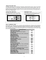
Battery Condition
icon
and the last functional setting when the machine
was turned off.
3. Release
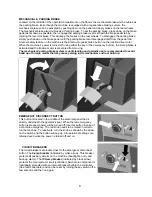
the
Parking Brake
as described in the
Mechanical & Parking Brake section
of this manual.
4. Select one of the four available
Modes
on the
Control Console
for the required task. Refer to the
Main Keyboard section
of this manual for a complete description of the functions.
5. Adjust
the
Solution Flow
and or
Brush pressure
to desired setting.
6. Determine the direction you need to travel by selecting
forward
or
reverse
on the
Directional
Switch.
The LCD screen will display an icon as described
LCD Section
in this manual. Vary the
pressure exerted on the accelerator pedal to propel the machine at the desired speed. Stepping on
the accelerator pedal activates.
17
Summary of Contents for SCV28
Page 1: ...SCV 28 32 RIDER SCRUBBER OPERATION SERVICE PARTS CARE ...
Page 3: ...3 ...
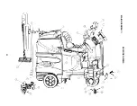
Page 31: ...EXPLODED VIEWS MAIN ASSEMBLY I 25 ...
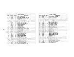
Page 32: ...26 ...
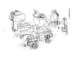
Page 33: ...MAIN ASSEMBLY II 27 ...
Page 34: ...28 ...
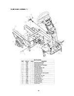
Page 35: ...MAINFRAME ASSEMBLY I 29 ...
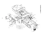
Page 36: ...MAINFRAME ASSEMBLY II 30 ...
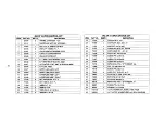
Page 37: ...31 ...
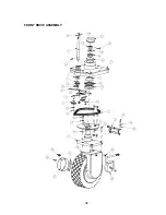
Page 38: ...FRONT DRIVE ASSEMBLY 32 ...
Page 39: ...33 ...
Page 40: ...STEERING ASSEMBLY 34 ...
Page 41: ...35 ...
Page 42: ...LCD HOUSING ASSEMBLY 36 ...
Page 43: ...SOLUTION TANK ASSEMBLY 37 ...
Page 44: ...38 ...
Page 45: ...ELECTRICAL PANEL ASSEMBLY 39 ...
Page 46: ...CONSOLE ASSEMBLY 40 ...
Page 47: ...RECOVERY TANK ASSEMBLY I 41 ...
Page 48: ...42 ...
Page 49: ...RECOVERY TANK II 43 ...
Page 50: ...DIVERTER ASSEMBLY 44 ...
Page 51: ...BATTERY BOX ASSEMBLY 45 ...
Page 52: ...PUMP ASSEMBLY 46 ...
Page 53: ...47 ...
Page 54: ...REAR AXLE ASSEMBLY 48 ...
Page 55: ...SQUEEGEE MECHANISM ASSEMBLY 49 ...
Page 56: ...REAR SQUEEGEE ASSEMBLY 28 50 ...
Page 57: ...51 ...
Page 58: ...REAR SQUEEGEE ASSEMBLY 32 52 ...
Page 59: ...53 ...
Page 60: ...28 CYLINDRICAL SCRUB DECK ASSEMBLY 54 ...
Page 61: ...55 ...
Page 62: ...28 DISC SCRUB DECK ASSEMBLY 56 ...
Page 63: ...57 ...
Page 64: ...32 CYLINDRICAL SCRUB DECK ASSEMBLY 58 ...
Page 65: ...59 ...
Page 66: ...32 DISC SCRUB DECK ASSEMBLY 60 ...
Page 67: ...61 ...
Page 68: ...CYLINDRICAL DECK AND SIDE SQUEEGEE MOUNTING 62 ...
Page 69: ...63 ...
Page 70: ...DISC SCRUBDECK AND SIDE SQUEEGEE MOUNTING 64 ...
Page 71: ...65 ...
Page 72: ...28 SIDE SQUEEGEE RIGHT SIDE 66 ...
Page 73: ...28 SIDE SQUEEGEE LEFT SIDE 67 ...
Page 74: ...32 SIDE SQUEEGEE RIGHT SIDE 68 ...
Page 75: ...32 SIDE SQUEEGEE LEFT SIDE 69 ...
Page 76: ...OFF AISLE WAND ASSEMBLY 70 ...
Page 77: ...71 ...
Page 78: ...PLUMBING DIAGRAM 72 ...
Page 79: ...WIRING DIAGRAMS POWER WIRING 73 ...
Page 80: ...INPUTS TO CONTROLLER 74 ...
Page 81: ...OUTPUTS FROM CONTROLLER 75 ...
Page 82: ...KEYBOARD WIRING 76 ...
Page 83: ...MACHINE SCHEMATIC 77 ...
Page 84: ...1 03 78 ...

