INSPECTION
Carefully unpack and inspect your
SCV Rider Scrubber
for shipping damage. Follow unpacking
instructions on shipping pallet. Each unit has been tested and thoroughly inspected before shipment. Any
damage is the responsibility of the delivery carrier who should be notified immediately.
ELECTRICAL
This machine is battery operated and designed to operate on 36 volts DC (6) 6-volt batteries.
BATTERIES
The recommended batteries are rated 370Ah (Minuteman P/N 956715).
We do not recommend mixing AMP hour capacities. Any alternate battery sets can be used if they equal
physical size and capacity. See page 13 for service and installation.
OPERATOR RESPONSIBILITY
Read this manual carefully before operating this machine.
The operator is responsible in taking care of the daily maintenance and check ups of the machine to keep
it in good working condition. The operator must inform the service mechanic or supervisor when the
scheduled maintenance intervals are required as stated in the
MAINTENANCE
section of this manual.
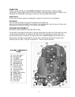
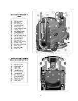
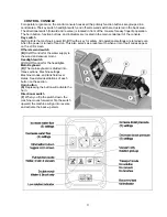
Before starting familiarize yourself with the machine and its controls (see “Machine Overview, Front”,
“Machine Overview, Rear”, “Operator Compartment”, “Control Console” diagrams).
MACHINE COMPONENTS
FRONT
A
B
C
D
E
F
G
H
I
J
K
L
M
N
O
P
Q
R
S
Front drive wheel
Side squeegee
Headlights
Accelerator pedal
Tilt-wheel lever
Steering wheel
Operator’s seat
Recovery tank lid
Recovery tank
Control console
Directional switch
Safety latch
Battery compartment
Solution tank
Electrical panel
Parking brake
Rear Squeegee
Rear wheel
Scrub deck
1
Summary of Contents for SCV28
Page 1: ...SCV 28 32 RIDER SCRUBBER OPERATION SERVICE PARTS CARE ...
Page 3: ...3 ...
Page 31: ...EXPLODED VIEWS MAIN ASSEMBLY I 25 ...
Page 32: ...26 ...
Page 33: ...MAIN ASSEMBLY II 27 ...
Page 34: ...28 ...
Page 35: ...MAINFRAME ASSEMBLY I 29 ...
Page 36: ...MAINFRAME ASSEMBLY II 30 ...
Page 37: ...31 ...
Page 38: ...FRONT DRIVE ASSEMBLY 32 ...
Page 39: ...33 ...
Page 40: ...STEERING ASSEMBLY 34 ...
Page 41: ...35 ...
Page 42: ...LCD HOUSING ASSEMBLY 36 ...
Page 43: ...SOLUTION TANK ASSEMBLY 37 ...
Page 44: ...38 ...
Page 45: ...ELECTRICAL PANEL ASSEMBLY 39 ...
Page 46: ...CONSOLE ASSEMBLY 40 ...
Page 47: ...RECOVERY TANK ASSEMBLY I 41 ...
Page 48: ...42 ...
Page 49: ...RECOVERY TANK II 43 ...
Page 50: ...DIVERTER ASSEMBLY 44 ...
Page 51: ...BATTERY BOX ASSEMBLY 45 ...
Page 52: ...PUMP ASSEMBLY 46 ...
Page 53: ...47 ...
Page 54: ...REAR AXLE ASSEMBLY 48 ...
Page 55: ...SQUEEGEE MECHANISM ASSEMBLY 49 ...
Page 56: ...REAR SQUEEGEE ASSEMBLY 28 50 ...
Page 57: ...51 ...
Page 58: ...REAR SQUEEGEE ASSEMBLY 32 52 ...
Page 59: ...53 ...
Page 60: ...28 CYLINDRICAL SCRUB DECK ASSEMBLY 54 ...
Page 61: ...55 ...
Page 62: ...28 DISC SCRUB DECK ASSEMBLY 56 ...
Page 63: ...57 ...
Page 64: ...32 CYLINDRICAL SCRUB DECK ASSEMBLY 58 ...
Page 65: ...59 ...
Page 66: ...32 DISC SCRUB DECK ASSEMBLY 60 ...
Page 67: ...61 ...
Page 68: ...CYLINDRICAL DECK AND SIDE SQUEEGEE MOUNTING 62 ...
Page 69: ...63 ...
Page 70: ...DISC SCRUBDECK AND SIDE SQUEEGEE MOUNTING 64 ...
Page 71: ...65 ...
Page 72: ...28 SIDE SQUEEGEE RIGHT SIDE 66 ...
Page 73: ...28 SIDE SQUEEGEE LEFT SIDE 67 ...
Page 74: ...32 SIDE SQUEEGEE RIGHT SIDE 68 ...
Page 75: ...32 SIDE SQUEEGEE LEFT SIDE 69 ...
Page 76: ...OFF AISLE WAND ASSEMBLY 70 ...
Page 77: ...71 ...
Page 78: ...PLUMBING DIAGRAM 72 ...
Page 79: ...WIRING DIAGRAMS POWER WIRING 73 ...
Page 80: ...INPUTS TO CONTROLLER 74 ...
Page 81: ...OUTPUTS FROM CONTROLLER 75 ...
Page 82: ...KEYBOARD WIRING 76 ...
Page 83: ...MACHINE SCHEMATIC 77 ...
Page 84: ...1 03 78 ...


