
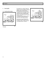
Introduction
Please be advised explicitly that
we cannot accept any legal is-
sues out of the contents of this
manual.
If repair work has to be perfor-
med make sure that only genui-
ne spare parts are used; only
genuine spare parts may gua-
rantee a dependable machine.
Valid as of: March 2005
Dear customer,
It is our desire that the good cha-
racteristics of the SW5X should
justify the confidence you demon-
strated by making this purchase.
Before first operation of your
SW5X, read these instructions
carefully. The manual provides
valuable information about opera-
tion, service and maintenance.
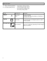
The symbol as used in this manual
identifies items relevant to safety.
Please observe the safety provi-
sions (see chapter 1).
Before first operation of the machine,
read these instructions and safety in-
formation carefully and comply with
them.
2
Summary of Contents for SW5X PB40PH
Page 1: ...SW5X Model PB40PL PB40PH Instruction Manual ...
Page 62: ...62 8 Spare parts ...
Page 64: ...64 ...
Page 66: ...66 ...
Page 68: ...68 ...
Page 70: ...70 ...
Page 72: ...72 ...
Page 74: ...74 ...
Page 76: ...76 ...
Page 78: ...78 ...
Page 80: ...80 ...
Page 82: ...82 ...
Page 84: ...84 ...
Page 86: ...86 ...
Page 88: ...88 ...
Page 90: ...90 ...
Page 92: ...92 ...
Page 94: ...94 ...
Page 96: ...96 ...
Page 98: ...98 ...
Page 100: ...100 ...
Page 102: ...102 ...
Page 104: ...104 ...
Page 106: ...106 ...
Page 108: ...108 ...
Page 110: ...110 ...
Page 112: ...112 ...
Page 114: ...114 ...
Page 116: ...116 ...
Page 118: ...118 ...
Page 120: ...120 ...
Page 122: ...122 ...
Page 123: ...Set of tires Pos Part No Description 1 99652900 Set of pneumatic tyres 123 ...
Page 124: ...124 ...
Page 126: ...126 ...
Page 128: ...128 ...
Page 130: ...130 ...
Page 132: ...132 ...
Page 134: ...134 ...
Page 136: ...136 ...
Page 138: ...138 ...
Page 140: ...140 ...
Page 144: ......


