background image


Installation and Safety Guide 


MIPV Leisure Series safety and 
installation guide for Multiple 
module photovoltaic systems for 
Motorhomes & Caravans. 

 
Products Codes: 

MIPV 013A (480W) 
MIPV 016A (330W) 


Summary of Contents for 013A

Page 1: ...Installation and Safety Guide MIPV Leisure Series safety and installation guide for Multiple module photovoltaic systems for Motorhomes Caravans Products Codes MIPV 013A 480W MIPV 016A 330W ...

Page 2: ...e to the roof of a motorhome or a caravan 7 12 Preparing the Roof 8 13 Laying the panel 9 14 Installing the Cabling 11 15 Position the Entry Gland Cowl 11 16 Installation wiring diagram for four module series parallel system 12 17 Installation wiring diagram for three module parallel connection system 13 18 Installing the Charge Controller 14 19 Connecting to the battery 14 20 Connecting the solar...

Page 3: ...6A 220W For other MiPV products please refer to the relevant instructions 3 Package Contents The MIPV Leisure series kit will contain the following items Product Reference MIPV013A MIPV016A MIPV solar module 4 3 Charge controller P1500B 1 Charge controller PC164015 1 Twin gland entry cowl 1 1 Red 4mm solar cable with MC4 connector 20m 15m Black 4mm solar cable MC4 connector 20m 15m Jumper cable MC...

Page 4: ...l regulations and law must be observed Under normal conditions a photovoltaic module is likely to experience conditions that produce more current and or voltage than reported at standard test conditions Accordingly the values of Isc and Voc marked on this module should be multiplied by a factor of 1 25 when determining component voltage ratings conductor current ratings fuse sizes and size of cont...

Page 5: ...iPV module to flex or twist excessively A bending radius in excess of 225mm can damage the module Technical Specification 8 Technical Specification There are no user serviceable parts in the MIPV Leisure Series solar kits DO NOT attempt to repair alter or remove any part of the equipment included in the kit MiPV PHOTOVOLTAIC MODULE SPECIFICATIONS F11F 110BM F13F 120B1 Nominal Power W 110 120 Open ...

Page 6: ...d result in injury MiPV Leisure Series with adhesive backing has a minimum shelf life of one year prior to installation when stored at temperatures below 24 C Leave all protective packing on the module until they have been installed on the roof Modules should be installed in a location where the wind uplift is at its minimum see figure 1 for example The ambient temperature at the time of installat...

Page 7: ... cleaners Please ensure the roof is fully dry before beginning the installation process Once the roof surface is dry use a pencil or a marker pen to mark out the four corners of the panel To ensure the panel is mounted squarely on the roof measure the distance from each corner of the panel to the edge of the vehicle roof We suggest the location such that the MiPV module junction boxes are as close...

Page 8: ... where the module is going to be located using the activator Ensure you extend the clean area to 10cm beyond the perimeter of the module figure 2 After cleaning the roof and applying the activator lay the panel in position ensuring the release liner is still in place and secure it to the roof using tape leaving one end of the panel free for at least the end half of the module figures 3 4 Only when...

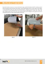
Page 9: ... section of 300mm of the white backing and fold it back over the still protected area figure 5 Carefully lay down this exposed section of the black adhesive adhering it to the roof ensure the module alignment does not change Press down firmly using a dry cloth to ensure that the adhesive backing makes full and even contact with the vehicle roof figure 6 Figure 5 Figure 6 ...

Page 10: ...olded back section of the release liner figure 7 and carefully pull back the release liner laying down the module as you proceed Press down using a dry cloth as you go working towards the free end of the module figure 8 When the module has been applied to the roof use a clean and dry soft cloth to work along the entire panel to ensure all parts of the panel are in full contactwiththeroofsurface Fi...

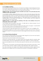
Page 11: ... to the male positive plug of the module Each MiPV module has two junction boxes marked for positive and for negative Connect the RED lead to the positive terminal and the black lead to the terminal Feed the cable tails through the two glands fitted in the supplied roof entry cowl non plugged end first DO NOT tighten the glands on the cable until the installation is complete Ensure you leave free ...

Page 12: ... Installation Manual v2 3 1 Electrical installation 12 16 Installation wiring diagram for four module series parallel connection systems Product MIPV 013A only Fuse not required for MIPV 013A product Figure 9 ...

Page 13: ...IPV Installation Manual v2 3 1 Electrical installation 13 17 Installation wiring diagram for three module parallel connection systems Product MIPV 016A only Fuse not required for MIPV 016A product Figure 10 ...

Page 14: ...le see figure 9 Connect the cables to the correct input terminals red ve black ve ensuring the all securing screws are tight Negative output to Battery Positive output to Battery Negative Input from Module Positive Input from Module Charge controller P1500B Charge controller PC164015 Figure 11 19 Connecting to the battery The MiPV Leisure solar products must be connected the leisure battery system...

Page 15: ...ment method to ensure all cables and plugs on the roof are fully secure and unable to move or vibrate when the vehicle is in motion Maintenance 21 Maintenance of MiPV solar modules Keeping MIPV Leisure Series Modules clean and unsoiled is critical to achieving maximum power output Whilst rain will clean off dust and soil we recommend that owners inspect and clean the modules regularly particularly...

Page 16: ...EA0301SHOT1 2 into 1 MC4 connector LEADR0306SHOT1 Isopropanol cleaner 50ml ACPPU0301SHOT1 White adhesive white 290ml DEKAS0301SHOT1 5m x 4 0mm solar cable Red LEADR0310SHOT1 5m x 4 0mm solar cable Black LEADR0311SHOT1 500 mm jumper connection c w MC4 connectors Black MULTI0308SHOT1 750 mm jumper connection c w MC4 connectors Black MULTI0310SHOT1 1000 mm jumper connection c w MC4 connectors Black M...

Page 17: ...DEESIDE FLINTSHIRE CH5 2NH WALES UNITED KINGDOM TELEPHONE 44 0 1244 892069 EMAIL CUSTOMER SERVICE MIPV CO UK WEBSITE WWW MIPV CO UK FOR FURTHER SUPPORT AND GUIDANCE ON INSTALLING MIPV MODULES CONTACT CUSTOMER SERVICE MIPV CO UK OR TELEPHONE 01244 892069 FOR FREE ADVICE AND GUIDANCE ...

Reviews: