18. Interface specifications
MiR1000 Shelf Lift User Guide (en) 12/2020 - v.2.1 ©Copyright 2019-2020: Mobile Industrial Robots A/S.
232
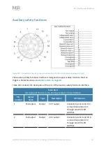
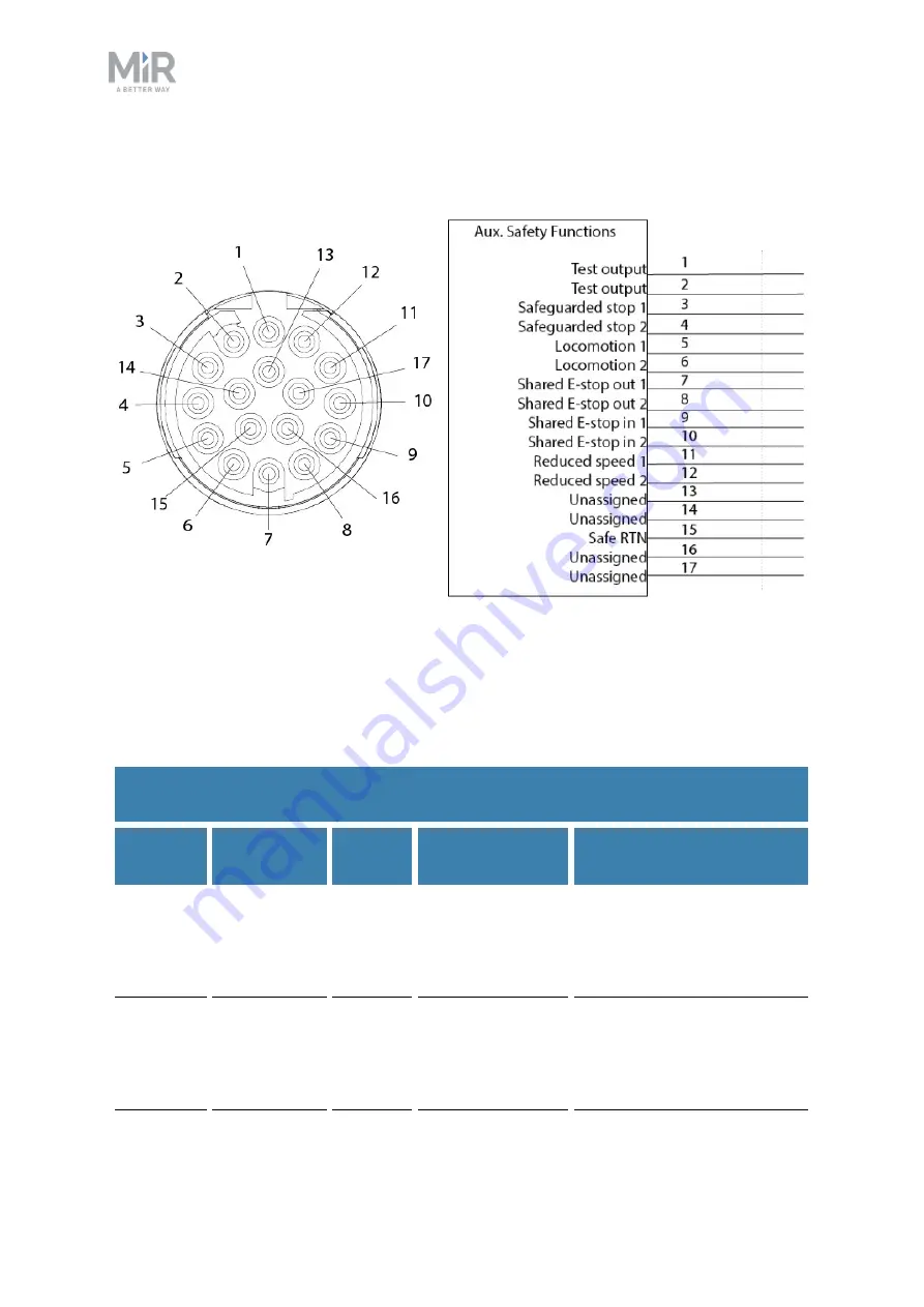
Auxiliary safety functions
Figure 18.5. Pin numbers: female connector viewed from the front (left) and wiring diagram (right).
The Auxiliary safety functions interface is designed to support safety functions that can
trigger a Protective stop—see
.
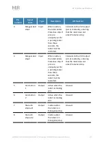
contains the description of the pins of the Auxiliary safety functions interface.
Pin
number
Signal
name
Type
Description
Lift function
1
Test output
Output
24 V output.
Connects to pins 3 and 9 in
a closed loop and pin 11
through one of the lift
switches.
2
Test output
Output
24 V output.
Connects to pins 4 and 10 in
a closed loop and pin 12
through one of the lift
switches.
Table 18.4.
Description of the pins in the Auxiliary safety functions interface


