18. Interface specifications
MiR250 Shelf Carrier User Guide (en) 03/2021 - v.1.4 ©Copyright 2021: Mobile Industrial Robots A/S.
239
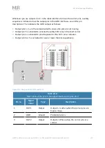
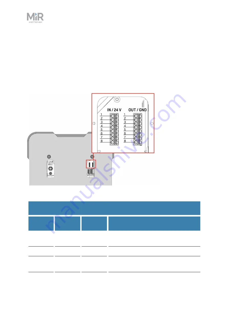
Whenever you use outputs 2 or 3 in the robot interface to move the carrier pins, a safety
sequence is initiated across the output pins in the GPIO interface—see
for pin
descriptions. The robot sets the GPIO outputs as follows:
1.
Output pins 1, 3, and 5 are deactivated to ensure the pins are not moving.
2.
Output pin 7 is activated to activate the safety STO relay in the shelf carrier.
3.
Output pin 1 is activated to provide power to the shelf carrier actuator.
4.
Output pin 3 or 5 is activated to raise or lower the pins respectively.
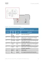
Figure 18.3. The pins of the GPIO interfaces.
Pin no.
Signal
name
Type
Description
1
OUT1
Output
Output 1. Is active when the carrier pins are
free to move.
2
GND
Ground
Protected return.
3
OUT2
Output
Output 2. When active, the carrier pins are
raised.
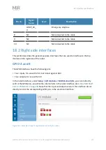
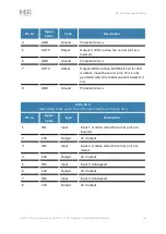
Table 18.2.
Description of the pins in the output interface in


