background image

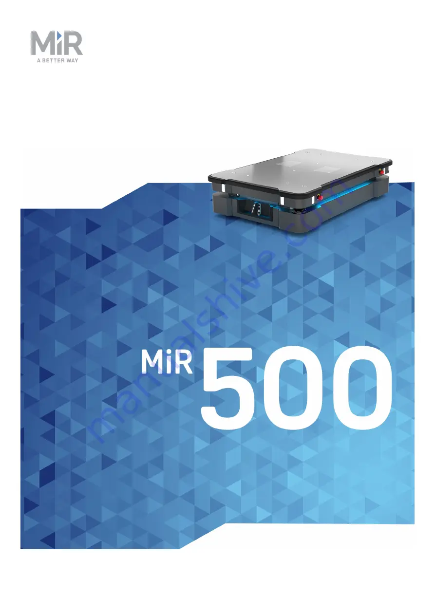
User guide

(en)

Date: 09/2019
Revision: v.1.3

Summary of Contents for 500

Page 1: ...User guide en Date 09 2019 Revision v 1 3 ...

Page 2: ... contents In addition the contents of the document are subject to change without prior notice Every precaution has been taken in the preparation of this manual Nevertheless MiR assumes no responsibility for errors or omissions or any damages resulting from the use of the information contained Copyright 2018 2020 by Mobile Industrial Robots A S Contact the manufacturer Mobile Industrial Robots A S ...

Page 3: ...tions 10 2 3 Intended use 12 2 4 Users 13 2 5 Foreseeable misuse 14 2 6 Risk assessment 15 2 7 Residual risks 15 2 8 Safety related functions and interfaces 16 2 9 Lithium battery 16 3 Product presentation 22 3 1 Main features of MiR500 22 3 2 Identification label 24 3 3 MiR500 control panel 25 3 4 MiR500 operating modes 27 3 5 External parts 29 3 6 MiR500 internal parts 36 3 Safety functions 49 3...

Page 4: ...terface 71 4 5 Driving the robot in manual mode 72 4 6 Checking the hardware status 74 4 7 Charging the robot 75 4 8 Shutting down the robot 77 5 Commissioning 78 5 1 Analysis of the work environment 78 5 2 Creating markers and positions 79 5 3 Operating hazard zones 85 5 4 Creating and configuring a map 86 5 5 Creating user groups and users 99 5 6 Creating dashboards 102 6 1 Updating MiR500 softw...

Page 5: ...Payload specifications 134 9 Disposal and environment 136 9 1 Battery disposal 136 10 Interface specifications 137 10 1 General purpose interfaces 137 10 2 Safety interfaces 145 10 3 Connector list 148 10 Troubleshooting 150 10 4 Shelf options are not available in the robot interface 150 10 5 Robot docking imprecisely or not docking at all to shelf 150 10 6 Robot turning strangely when docking 150...

Page 6: ... is in print in the box with the robots Quick starts are available in multiple languages User guides provide all the information you need to operate and maintain MiR robots User guides are available in multiple languages Risk Analysis Guides include guidelines on how to create a risk assessment of your robot solution Commissioning guides describe how to commission your robot safely and prepare it ...

Page 7: ...regarding MiR products Distributor site How to http www mobile industrial robots com en account how to This page contains how to guides that describe how to perform specific tasks with MiR products Distributor site Troubleshooting https www mobile industrial robots com en account troubleshooting This page contains troubleshooting guides to solve common issues with MiR products MiR500 product page ...

Page 8: ...tion SW HW 1 2 2019 07 11 New sections Create mission Mission editor Lift modifications Updated status lights Added notice regarding using smart phones in flight mode for manual driving 2 7 0 1 0 1 3 2019 10 08 New section Updating MiR500 software 2 7 x 1 1 Revision Release date Description SW HW 1 0 2020 03 01 First edition 2 9 X 1 0 ...

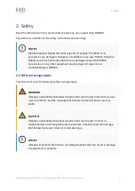
Page 9: ...R500 accessories or any other equipment due to programming errors or malfunctioning of MiR500 2 1 Safety message types This document uses the following safety message types WARNING Indicates a potentially hazardous situation that could result in death or serious injury Carefully read the message that follows to prevent serious injury or death CAUTION Indicates a potentially hazardous situation tha...

Page 10: ...WARNING The protective fields on the site of MiR 250 is only 10 15 mm MiR500 may drive over the feet of personnel Risk of injury All personnel must be instructed to wear safety shoes near an operating robot WARNING Contact with live parts can cause electric shock Do not touch any internal components of MiR500 while it is powered WARNING Unstable mounting of the UR robot arm Risk of injury Make sur...

Page 11: ...ne s eye do not rub the eye Rinse well with water and immediately seek medical care If left untreated the battery fluid could cause damage to the eye Use only the original charger cable charger or charging station and always follow the instructions from the battery manufacturer Do not touch damaged batteries with bare hands Only qualified personnel should handle damaged batteries with suitable Per...

Page 12: ...t the environmental conditions in which the MiR500 robot should operate see Technical specifications on our website MiR500 is intended to be commissioned according to Commissioning on page 78 and prepared to the environment according to the guidelines This is a prerequisite for safe usage of MiR500 MiR500 is designed for and all risks are considered when used with one of the following types of top...

Page 13: ...transfer station 2 4 Users MiR500 is only intended to be used by personnel that have received training in their required tasks There are three types of intended users for MiR500 commissioners operators and direct users Commissioners Commissioners have received extensive training in the full use of MiR500 and have the following main tasks Commissioning the product This includes creating maps and re...

Page 14: ...intended use is deemed as misuse This includes but is not limited to Using MiR500 to transport people Using MiR500 on steep surface grades such as ramps Driving MiR500 on cross slopes Exceeding the maximum payload Using the emergency button for anything other than emergency stops It is not designed for frequent use Positioning or fastening load incorrectly according to the specifications See Paylo...

Page 15: ...er relevant standards to conduct the risk assessment In EN 1525 clause 4 there is a list of significant hazards hazardous situations and events that can be used for inspiration 2 7 Residual risks Mobile Industrial Robots has identified the following potential hazards that commissioners must inform personnel about and take all precautions to avoid You risk being run over drawn in trapped or impacte...

Page 16: ...or Each safety function and interface is designed according to the standard ISO 13849 1 The safety related functions and interfaces are selected to support compliance with EN 1525 See Safety related functions and interfaces above and Safety related electrical interfaces on page 63 2 9 Lithium battery This section describes how to change the battery on MiR500 MiR500 is supplied with a fast swap rem...

Page 17: ...to generate heat explode or ignite Do not allow the battery to get wet In the event the battery leaks and the fluid gets into one s eye do not rub the eye Rinse well with water and immediately seek medical care If left untreated the battery fluid could cause damage to the eye Use only the original charger cable charger or charging station and always follow the instructions from the battery manufac...

Page 18: ...2 Safety MiR500User guide en 09 2019 v 1 3 Copyright 2018 2020 Mobile IndustrialRobots A S 18 To change the battery 1 Push the two black buttons on the back of the robot 2 Pull the hatch ...

Page 19: ...User guide en 09 2019 v 1 3 Copyright 2018 2020 Mobile IndustrialRobots A S 19 3 To access the battery first pull the bottom metal lever and push the top lever as shown in the photo 4 Then press down on the top lever ...

Page 20: ...2 Safety MiR500User guide en 09 2019 v 1 3 Copyright 2018 2020 Mobile IndustrialRobots A S 20 5 Separate the battery connector from the robot connector ...

Page 21: ...service life of the battery The battery should be stored in an area with at maximum of 80 non condensing relative air humidity The battery should not be exposed to nor submerged in any liquid Charge the battery before storage The battery is maintenance free but may be cleaned occasionally When cleaning the battery must be removed from any power source Only use a dry and soft cloth to clean the hou...

Page 22: ...ization and navigation via a map which can be created or imported the first time the robot is used The internal map contains defined locations office product delivery production hall etc that are used for logistical planning While operating the safety laser scanners ensure that the robot avoids dynamic obstacles people furniture that are not mapped With a MiR Charge 48V the robot can charge automa...

Page 23: ...to operation and monitoring of the robot and can be programmed without any prior experience Different user group levels and tailored dashboards can be set up to suit the different users Alert for lost If the robot enters a situation where it is unable to find a path to its destination it stops turns on the yellow purple running error light and a customer defined catch action may be used to alert p...

Page 24: ...Pallet Rack with MiR500 EU Pallet Lift The lift places and picks up EU pallets from the rack autonomously MiR 250 Cart Carrier A top application that allows MiR500 to tow carts with a payload of up to 500 kg To read more about the add ons go to www mobile industrial robots com 3 2 Identification label The identification label of MiR500 is placed above the MiR controller behind the rear maintenance...

Page 25: ... Operating mode key The Operating mode key lets you switch between operating modes Left position Autonomous mode Puts the robot in Autonomous mode Middle position Stop Stops the robot The robot blocks the wheels you cannot start a mission or drive the robot manually Right position Manual mode Puts the robot in Manual mode For more information on operating modes see MiR500 operating modes on page 2...

Page 26: ...let the robot continue operating Color indication Red The robot is on Restart Pressing this button Clears the emergency stop state Lets the robot continue operating after the Stop button was pressed Lets the robot continue operating after powering up or after the operating mode change Color indication Blinking red The robot is waiting for a user action clear the emergency stop state acknowledge th...

Page 27: ...t in manual mode on page 72 Autonomous mode In this mode the robot executes the programmed mission After switching the key to this mode you can remove the key and the robot will continue driving autonomously In autonomous mode the joystick is disabled in the robot interface Muting of the personnel detection means When performing tasks that require the robot to move very close to surrounding object...

Page 28: ...ts A S 28 In the robot interface select Mute personnel detection meansin the Joystick control In the prompt dialog select Yes to acknowledge the muting of personnel detection means The status and the signal lights start flashing yellow the robot is ready to drive with muted personnel detection means ...

Page 29: ...3 Product presentation MiR500User guide en 09 2019 v 1 3 Copyright 2018 2020 Mobile IndustrialRobots A S 29 3 5 External parts ...

Page 30: ...3 Product presentation MiR500User guide en 09 2019 v 1 3 Copyright 2018 2020 Mobile IndustrialRobots A S 30 This section presents the parts of MiR500 that are visible on the outside ...

Page 31: ...p 9 3D depth cameras two pcs detect objects in front of the robot see Sensor system on page 51 3 Signal light eight pcs two on each corner see Sensor system on page 51 10 Front maintenance hatch opens to front compartment see MiR500 internal parts on page 36 4 Rear maintenance hatch opens to rear compartment see MiR500 internal parts on page 36 11 Front safety laser scanner see Sensor system on pa...

Page 32: ...en hazard 1 Signal light eight pcs two on each corner see Sensor system on page 51 8 Button interface 2 Proximity sensors eight pcs two in each corner behind corner cover see Sensor system on page 51 9 Top plate 3 Rear maintenance hatch opens to rear compartment see MiR500 internal parts on page 36 10 Bumpers 4 Nonoscan3 safety laser scanner see Sensor system on page 51 11 3D cameras 5 Left cover ...

Page 33: ...v 1 3 Copyright 2018 2020 Mobile IndustrialRobots A S 33 6 Left cover plate access to power interface GPIO interface and Ethernet interface 13 Status light on all four sides of the robot see Sensor system on page 51 7 Brake release MiR500 external parts ...

Page 34: ...3 Product presentation MiR500User guide en 09 2019 v 1 3 Copyright 2018 2020 Mobile IndustrialRobots A S 34 MiR500 top cover ...

Page 35: ...3 Product presentation MiR500User guide en 09 2019 v 1 3 Copyright 2018 2020 Mobile IndustrialRobots A S 35 View of MiR500 from the top ...

Page 36: ...on mounting top modules see Mounting a top module on page 119 2 M12 lifting holes one in each corner Used for fixation of transportation eye bolts 1 M8 mounting holes for fixation of top module For more information on mounting top modules see Mounting a top module on page 119 3 6 MiR500 internal parts Most internal parts of MiR500 are reached through maintenance hatches that open to different comp...

Page 37: ...020 Mobile IndustrialRobots A S 37 Front compartment The front compartment holds the electronic components that may need regular service or replacement such as PC main control board and safety PLC To open the front compartment 1 Push the two white buttons and pull the hatch ...

Page 38: ... v 1 3 Copyright 2018 2020 Mobile IndustrialRobots A S 38 2 Turn the two levers 180 The right lever goes from top to bottom and the left lever goes from bottom to top Then pull out the compartment drawer while holding underneath it and lifting slightly ...

Page 39: ...artment contains the following components 1 Cable chain 5 Loudspeaker 2 Safe Torque Off contactors 6 Power board controlling power distribution for motor controller PC and safety PLC 3 Access point Router 7 Motor controller carrier board contains motor controllers and controller for proximity sensors and light indicators 4 Robot computer 8 Safety PLC ...

Page 40: ...oduct presentation MiR500User guide en 09 2019 v 1 3 Copyright 2018 2020 Mobile IndustrialRobots A S 40 Rear compartment The rear compartment holds the robot s battery and most of the accessible components ...

Page 41: ...3 Product presentation MiR500User guide en 09 2019 v 1 3 Copyright 2018 2020 Mobile IndustrialRobots A S 41 To open the rear compartment 1 Push the two whiteblack buttons ...

Page 42: ...sentation MiR500User guide en 09 2019 v 1 3 Copyright 2018 2020 Mobile IndustrialRobots A S 42 2 Pull the hatch 3 To access the battery first pull the bottom metal lever and push the top lever as shown in the photo ...

Page 43: ...3 Product presentation MiR500User guide en 09 2019 v 1 3 Copyright 2018 2020 Mobile IndustrialRobots A S 43 4 Then press down on the top lever ...

Page 44: ...ng connection interface for external charger 2 Battery disconnect switch shown in Off position 6 Battery with connector main power to the robot 3 Connector for status light band 7 Connection interface for MiR Controller 4 Brake release switch shown in On position When turned off the brakes are released and the robot can be pushed manually Side compartments The side compartments contain the right a...

Page 45: ...resentation MiR500User guide en 09 2019 v 1 3 Copyright 2018 2020 Mobile IndustrialRobots A S 45 To open a side hatch turn the two screws 90 counterclockwise with a hex keyflat head screwdriver and pull the hatch ...

Page 46: ...t and right hand side compartments contain the following components the same on both sides 1 Connector for status light band 2 Drive wheel Top compartments The two top compartments hold interfaces to external units for example MiR500 EU Pallet Liftor MiR500 Pallet Lift To open a top compartment remove the four screws and lift off the top cover ...

Page 47: ...3 Product presentation MiR500User guide en 09 2019 v 1 3 Copyright 2018 2020 Mobile IndustrialRobots A S 47 The two top compartments contain interfaces for top applications and added safety functions ...

Page 48: ...lRobots A S 48 Top compartment components The top compartments contain the following electrical interfaces for top applications For detailed information see Interface specifications on page 137 1 Ethernet 4 Auxiliary emergency stop 2 GPIO General purpose I O 5 Auxiliary safety functions 3 Power ...

Page 49: ... an autonomous and collaborative robot that relies on localization techniques to orient itself in its environment The robot uses path planning that consists of two parts a global planner that does the general path planning between two positions and a local planner that causes the robot to follow the global path and also take into account the surroundings so that the robot avoids dynamic obstacles ...

Page 50: ...he robot sees the surrounding environment Figure 3 1 The laser scanners detect a dynamic object in the bottom left corner Figure 3 2 Human eyes see the chair and surrounding details Figure 3 3 Laser scanners of the robot will only detect parts of the chair Here the scanners detect the four legs of the chair in the upper left corner of the map ...

Page 51: ... or holes in the floor or any type of glass The limitations of the safety laser scanners shall be considered during the preparations of the environment the robot will function in 3 8 Sensor system Collaboration between the robot s internal and external sensors ensures that the robot can navigate in the work environment and most importantly secures that it can operate safely among people and object...

Page 52: ...sensitive protective device In this guide the term safety laser scanner is used Scanner functions Two safety laser scanners diagonally placed on front and rear corners of the robot scan their surroundings Each safety laser scanner has a 270 field of view overlapping and thus providing a full 360 visual protection around the robot The safety laser scanners serve three purposes They are used for map...

Page 53: ... The two safety laser scanners together provide a full 360 view around the robot When in motion the safety laser scanners continuously scan the surroundings using a distance of up to 40 m while taking into account and weighing the viewed objects in a so called particle filter When mapping the safety laser scanner s view is reduced to 20 m to ensure that maps will get the highest possible quality F...

Page 54: ...ically selected based on the speed of MiR500 A person or object within an active protective field will bring the robot to a protective stop and the robot will remain stopped until the protective field is free The commissioner can change the field sets if for instance the surface requires a longer breaking distance See Brake test See the how to guide How to adjust the field sets on MiR250 500 1000 ...

Page 55: ...Muted personnel detection means When docking to markers the protective fields are muted to avoid unintended activation Muted protective fields is part of the drive mode Muted personnel detection means where the robot also slows down the speed For more information see MiR500 operating modes on page 27 3D cameras Two 3D depth cameras positioned on the front of the robot detect objects in front of th...

Page 56: ...0User guide en 09 2019 v 1 3 Copyright 2018 2020 Mobile IndustrialRobots A S 56 The following illustrations show the fields of view of the cameras Figure 3 7 The two 3D cameras can see objects up to 1700 mm above floor height ...

Page 57: ...3 Safety functions MiR500User guide en 09 2019 v 1 3 Copyright 2018 2020 Mobile IndustrialRobots A S 57 Figure 3 8 The two 3D cameras have a horizontal field of view of 114 ...

Page 58: ... detect objects close to the floor Internal sensors The internal sensor system of the robot consists of the following components Gyroscope IMU Measures the orientation and angular velocity of the robot Motor encoder Provides closed loop feedback signals by tracking the speed and or position of the motor shaft Accelerometer Measures non gravitational acceleration Wheel encoders Detect wheel movemen...

Page 59: ...A S 59 signal the current status of the robot Signal lights The signal lights at the front and back of the robot show if the robot is about to turn a corner or go backwards Front lights are white and rear lights are red Right and left turns are indicated by blinking 1 Status lights 2 Signal lights ...

Page 60: ... battery reaches a critically low level of power 0 1 the corner LED lights flash red Signal lights Signal lights are used to indicate the robot s immediate motion plans by signaling forwards backwards braking and left right turns The signal lights work similarly to lights used on cars white at the front red at the back and indicating a left or right turn by blinking When the robot drives with mute...

Page 61: ...l built in safety related functions that are used to ensure safe operation in the environment it is designed to be used in Advanced control software ensures that the drive patterns are within safety related limits and thereby avoid triggering a safety function Violations of limits will hence only occur in exceptional cases Nevertheless if a limit is violated the safety system issues a category 0 s...

Page 62: ...nsists of interlock switches that detect if the lift modules are in the lowest position or not The input can be used for a customized top module manipulator when a MiR500 Pallet Lift or MiR500 EU Pallet Lift is not installed The safe load position safety function must be manually deactivated by activation of the restart button Overspeed avoidance The safety system monitors if the speed of each mot...

Page 63: ...y activation of the restart button 3 11 Safety related electrical interfaces The robot is equipped with several safety related electrical inputs and outputs All safety related electrical inputs and outputs are dual channel They are safe when low meaning the emergency stop is not active when the signal is high 24V Safety related electrical inputs This section contains the safety related electrical ...

Page 64: ...ad handling position This input can be used to apply the safe load position safety function on a system with customized top modules or manipulators A variety of sensors or interlock switches that detect load handling position or position of load can be connected and thereby enable the safe load position safety function Safety related electrical outputs This section contains the safety related elec...

Page 65: ...tarted with MiR500 NOTICE Read Safety on page 9 before powering up the robot 4 1 In the box This section describes the content of the MiR500 box The box contains 1 The MiR500 robot 2 MiR500 document folder containing the printed documents and the USB flash drive 3 Printed documents MiR500 Quick Start MiR username and passwords CE declaration of conformity ...

Page 66: ...t Lift Operating Guide MiR username and passwords CE declaration of conformity 4 2 Unpacking MiR500 This section describes how to unpack MiR500 Keep the original packaging for the future transportation of the robot The robot is shown with a EU pallet lift 1 Place the box with the robot so that there is 3 m of free space at the front or the back of the box This is necessary since the robot drives o...

Page 67: ...en 09 2019 v 1 3 Copyright 2018 2020 Mobile IndustrialRobots A S 67 3 Remove the lid from the box 4 Take the folder with the printed documents and the USB drive out of the box 5 Remove the walls of the box and the protective foam blocks ...

Page 68: ...User guide en 09 2019 v 1 3 Copyright 2018 2020 Mobile IndustrialRobots A S 68 6 Cut the protective straps 7 Place the lid of the box so that you can use it as a ramp Align the lid so that it is flush with the base of the box ...

Page 69: ...020 Mobile IndustrialRobots A S 69 8 Remove the wheel stop board from the pallet to let the robot drive on the ramp 4 3 Powering up Follow these steps to power up MiR500 1 Open the rear maintenance hatch To open the hatch push two buttons on the hatch and pull the hatch ...

Page 70: ... the battery disconnect switch to position ON 3 The On Off button turns blue See MiR500 control panel on page 25 4 Close the maintenance hatch 5 Ensure that all four emergency stop buttons are in the released state Turn an emergency stop button clockwise to release it 6 Press the On Off button for five seconds ...

Page 71: ...ant red 4 4 Connecting to the robot interface When the robot is on it enables the connection to its WiFi access point The name of the access point appears in the list of available connections on your PC tablet or phone NOTICE The username and password for the robot s WiFi access point and for accessing the web interface are in the MiR username and passwords document The document is in the box with...

Page 72: ...20 Mobile IndustrialRobots A S 72 2 In a browser go to the address mir com and sign in 3 Switch to manual mode and drive the robot down the ramp see section Driving the robot in manual mode on page 1 4 5 Driving the robot in manual mode To drive the robot in Manual mode ...

Page 73: ...de with any humans or objects when driving with muted personnel detection means 1 Put the Operating mode key into the Manual mode turn to the right 2 In the robot interface select the joystick icon The joystick control appears 3 Select Manual control The Restart button on the robot starts blinking 4 Press the Restart button The status lights turn blue indicating that the robot is in Manual mode No...

Page 74: ...lRobots A S 74 5 Drive the robot using the joystick 4 6 Checking the hardware status To check that all hardware components work as intended follow the steps below 1 Sign in to the robot interface See the section Connecting to the robot interface on page 1 2 Go to Monitoring Hardware health ...

Page 75: ...ve green dots on the left For more information see Hardware health in MiR Robot Interface 2 0 Reference Guide 4 7 Charging the robot A charger cable and an external charger is not part of the MiR500 standard delivery To charge MiR500 using the cable charger 1 Open the maintenance hatch at the back of the robot To open the hatch push two buttons on the hatch and pull the hatch ...

Page 76: ...n 09 2019 v 1 3 Copyright 2018 2020 Mobile IndustrialRobots A S 76 2 Connect the charger cable to the charging connector on the robot For information about the charging time see the robot specifications at www mobile industrial robots com ...

Page 77: ...he On Off button for five seconds 3 The robot starts the shutdown process Status lights blink yellow the On Off button blinks red 4 When the robot finishes the shutdown process the status and the signal lights go off the On Off button turns blue If shutting the robot down for transportation or service repair the battery disconnect switch must be turned off as well and the battery cable disconnecte...

Page 78: ...njury There must be an escape zone of 0 5 m with a height of 2 1 m on each side of the robot where the robot operates Surfaces The floor surface of the work environment must be dry MiR500 functions on many different types of surfaces but some materials can affect the performance and safety of the robot such as very thick carpets or slippery floors The minimum required frictional coefficient for th...

Page 79: ...ers and positions Positions Positions are defined as X Y coordinates on the map and are used as parts of missions Positions are used either as destination positions or as via positions on a route There are different types of positions depending on whether the robot is part of a fleet or drives with top applications but the standard position that is available in all MiR applications is the Robot po...

Page 80: ...020 Mobile IndustrialRobots A S 80 A V marker is a small V shaped marker A VL marker is a larger marker that generally is more precise than V markers L markers make it possible for the robot to dock sideways Charging stations Shelves and Pallet racks also have markers ...

Page 81: ...his section explains how to create a charging station marker on a map Before creating the marker you must ensure that the robot is localized correctly on an active map If in doubt you can check if the red lines representing the laser scanner line match the black lines on the map as shown in Figure 5 1 Figure 5 1 The red lines represent what the laser scanners detect The robot is correctly localize...

Page 82: ... marker 2 4 In the Create marker window enter a name for the marker and select Type This is the name of the 48V Charging station in the robot interface 5 Select Detect marker The Detect marker function tracks the position of the charging station using the on the charger and automatically sets the X Y and Orientation values in the robot enabling it to dock to the charging station ...

Page 83: ... that the front safety laser scanner is positioned in front of the of the charging station Creating a robot position This section explains how to create a robot position on a map Before creating the position you must ensure that the robot is localized correctly on an active map If in doubt you can check if the red lines representing the laser scanner line match the black lines on the map as shown ...

Page 84: ...itor of the map where you want to create a marker This is done by navigating to Setup Maps and selecting Edit next to the map you would like to work on 2 In the Object type drop down menu select Positions and then select Draw a new position 3 Click on the map where you want the position to be and choose in which direction you want it to face ...

Page 85: ...edit a position or send a robot to the position by clicking on it in the map 5 3 Operating hazard zones Why marking is required When docking to the robot mutes its Personnel detection means temporarily This includes turning off the protective field sets around the robot The muting starts when the robot reaches the entry position approximately one meter from To indicate this to people nearby MiR Fl...

Page 86: ...ked to indicate an operating hazard zone illustrated by the striped yellow and black line CAUTION If you want to dock and or undock to the from both ends or if you want to undock the by going forward the operating hazard zone needs to be of equal size on both ends of the 5 4 Creating and configuring a map It is vital to create a robust reliable map for the robot as the map is the basis for the rob...

Page 87: ...ng Place the robot close to a wall where the laser scanners have a good amount of coverage for example near a corner What to avoid Starting the mapping with the robot in a very open space Getting the robot stuck close to walls or objects as you will have to push it away manually Create a new map 1 Sign in to the robot interface and Go to Setup Maps 2 Select Create map 3 Name the map and choose a s...

Page 88: ...019 v 1 3 Copyright 2018 2020 Mobile IndustrialRobots A S 88 5 Click the three dots in the top left corner and start recording by selecting Record and overwrite 6 In the In the upper right corner select the joystick icon Select Manual control ...

Page 89: ...g in a circular pattern around the perimeter of the working environment c When reaching long corridors whith few obstacles let the robot stay in position for approx 5 6 seconds before moving down the corridor d Walk behind the robot as you map e End the mapping pattern in the same place you started it The joystick switches to medium speed when used during mapping This ensures better coverage of th...

Page 90: ...nd it Maps must be aligned along the X Y axis because the robot uses the X Y axis to plan its routes Drag the map to rotate it On desktop computers holding the Shift key when dragging the map rotates the map in increments of 11 25 degrees When the map is aligned select the Ok in the upper left corner of the mapping window 10 Clean the map by drawing walls and floors and by erasing dynamic obstacle...

Page 91: ...a new line and mark on the map where there are walls or other static landmarks It is a good idea to draw walls on top of all the walls and static objects the robot has recorded with its laser scanners This will help the robot s localization and make the map more clean Select the Finish current line when finishing a wall ...

Page 92: ...floors layer by selecting Floors The grey areas on the map is where there is missing a floor but often the easiest thing to do is to add a whole new floor on top of the existing one Because you are on the floors layer the new floor will not have an effect on objects on the walls layer Draw the floor area on the map Select the check mark ...

Page 93: ... on the map The erase tool will only erase walls when you are on the walls layer Select the check mark 14 Once you ve cleaned the map it should look neat and only contain static landmarks Select save to save the map Use zones on the map Adding zones to the map helps organize robot traffic There are several different zones that can optimize the preferred paths and driving behavior of the robot ...

Page 94: ...cles can trigger protective stops again This zone is useful in narrow doorways Speed zones the robot slows down or increases its speed when driving in the zone Sound and light zones the robot either blinks and or makes a sound to catch attention Planner zones the robot can ignore data from the laser scanners and localize with encoders decrease the field of view to run smoothly in populated areas o...

Page 95: ...s in the floor as Forbidden zones on the map Low hanging fixtures Issue MiR500 will not see the low hanging fixture This could be dangerous with a top module attached to the robot Solution Mark the area where the low hanging fixture is located as a Forbidden zone Highly dynamic areas A highly dynamic area is an area where objects are moved frequently This could be a production area where pallets a...

Page 96: ...urple can be used in highly dynamic areas to solve issues with re planning of paths Doorways and ramps Going through narrow doorways can cause problems for the robot or for the people working near the robot as they might not see the robot coming Going up a ramp can cause similar problems because of the upwards angle Issue The robot stops because a narrow doorway is seen as an obstacle Due to senso...

Page 97: ...be placed on the narrow doorway to force the global planner to make a path through the corridor Shelves Shelves are often placed in a certain height above the floor on four or more posts and will often appear as dots on a map for the robot This may cause the robot to believe that there is enough space if the posts are far enough apart below the shelf to pass through MiR500 will then plan a path un...

Page 98: ... of the robot and the pallet rack Issue MiR500 mutes the personnel detection means temporarily when docking to a pallet rack This could cause a dangerous situation Solution Follow the mounting guidelines and mark the area around the pallet rack with tape or similar as an operating hazard zone see Operating hazard zones Inform users of or near the robot of the safety issues regarding the pallet rac...

Page 99: ...ce can be locked by the commissioner The locked parts are typically related to the safety of the robot system and change of the settings can violate the CE marking of the robot It is important to analyze and consider who is Working directly with MiR500 as direct users or operators Working indirectly with MiR500 as indirect users Responsible for MiR500 as commissioner How many different users are t...

Page 100: ...issioning MiR500User guide en 09 2019 v 1 3 Copyright 2018 2020 Mobile IndustrialRobots A S 100 Under Set permissions you can select the specific parts of the robot interface that the user group has access to ...

Page 101: ... Create users In Setup Users you can create new users and select What user group they belong in If they are single dashboard users with no access to other parts of the interface than to control the robot from a dashboard If they should be allowed quick access to the interface via a four digit PIN code ...

Page 102: ...ner Create new user groups Commissioner Assign missions Direct user System settings Commissioner 5 6 Creating dashboards To make the user experience as easy and simple as possible you can build up a unique dashboard for each user Dashboards are an easy way for different user groups to control the robot giving direct access to their individual key functions Consider the following based on previous ...

Page 103: ...ence Guide in the MiR Robot Interface A dashboard is made up of a number of widgets each representing a feature in the system for example a particular mission the map the robot is operating in or the current mission queue The system comes with a default dashboard and users can create an unlimited number of additional customized dashboards To create a custom dashboard 1 Go to Dashboards Dashboards ...

Page 104: ...ulling the arrow in the lower right hand corner and rearrange their order by click dragging c Some widgets require further settings For example you must select a particular mission for mission buttons To do this click the pen icon in the lower left hand corner and select the wanted action d Select Save to save the dashboard The dashboard is now available under Dashboards For details on the widgets...

Page 105: ... new features Each software release is issued with a release note explaining the content of the update and its target audience Follow the steps below to update MiR500 software 1 Go to the MiR Distributor site and sign in with your credentials 2 Select Download and select MiR500 in the product drop down menu 3 Download the desired version of MiR Software Robot Hook Fleet 2 version x x x 4 Connect y...

Page 106: ...ialRobots A S 106 5 Navigate to System Software versions and select Upload software 6 Locate and select the downloaded software package It may take a few minutes for the package to successfully upload 7 Once the software is uploaded turn the robot off and then on again ...

Page 107: ...s Therefore this section presents some key examples of good practices when creating missions 6 2 Creating a mission This section describes what a mission is and how to make one MiR robots function through missions that the user creates A mission is made up of actions such as move actions logic actions cart pick up delivery and sounds which can be put together as building blocks to form a mission w...

Page 108: ...tic battery recharge Actions and missions are grouped in the same menus You can select which menu group the new mission should belong to or you can use the default Missions group Missions have this icon and actions have this icon The robot interface also comes with a set of default missions that you can use and or modify The form contains the following elements NameThe name must be unique and is u...

Page 109: ...tain actions from several groups When you save the new mission it will be placed in the selected group and can be used as a separate mission or as an embedded mission in other missions Create mission group If you don t want to use any of the default group names you can create your own group s and save missions here New groups will be shown in the top bar next to the default groups and contain any ...

Page 110: ...ssions are placed together with actions in the group to which you append them and can be distinguished from actions by a target icon next to their names When you have picked the actions you want in your mission do the following 1 Drag the actions up or down with the four headed arrow at the far left of the action line to sort them in the desired order The actions are executed in a top to bottom or...

Page 111: ...the name of the mission and select the gearwheel Save mission When you have completed the missions by adding all actions and sorted them in the desired order click Save to save the mission Save mission as You can save a copy of a mission and give it a new name That way it is easy to create a new mission based on the settings of an existing one ...

Page 112: ...shelf mission To create the mission it is assumed you have completed the following Enabled the shelf feature as described in Enable MiR500 feature Created a shelf position as described in Setting cartshelf positions on the map Placed a physical shelf at the shelf position 1 Go to Setup Missions Select Create mission 2 Give the mission a name for example Pick up and place shelf Select the group and...

Page 113: ... Move menu select Move d In the Shelf menu select the Place MiR500 1000 Shelf template mission The mission dialog should look like this The following steps describe which parameters each action should be set to To modify the parameters select the gearwheel of the action in question to open the dialog of that action 4 Under Move to select the shelf position you want to dock to 5 Under Position type...

Page 114: ... by MiR see Shelf specifications you can create your own footprint see Create footprint 9 Under Mute front Mute rear and Mute sides select if you want the safety scanners to be muted on the front rear or sides while undocking This can be necessary if the shelf is located near other obstacles see Mark potentially hazardous floor areas 10 Under Undocking distance choose the undocking distance in met...

Page 115: ... shelf is located near other obstacles see Mark potentially hazardous floor areas The safety scanners are muted to the sides by default in the place shelf template so the robot doesn t go into protective stop when driving away from the shelf 14 Under Footprint select the footprint that matches your shelf 15 Under Undocking distance select the undocking distance in meters A negative value makes the...

Page 116: ...ith the product Know the robot s limitations and possibilities Can solve common issues Recognize common errors Know who to contact if they experience issues Inform users Informing users about MiR500 and its functions at a level that matches their user type direct indirect etc will help ensure a safe and successful installation of the robot Useful information at different levels could be Safety zon...

Page 117: ...robot Manual driving Get familiar with dashboard and interface Blocked paths Robot getting stuck in emergency stop when getting pushed into objects or objects being placed close to robot How to recognize that the robot has a problem with charging Narrow paths where the robot might find it difficult to pass This illustrates the importance of having wide and clear paths for optimal driving of robot ...

Page 118: ...s running perfectly but it might also be because they have problems and gave up on the robot Urge them to contact you with problems especially in the beginning Contact customers yourself in the beginning to make sure they are happy and the product is working satisfactorily A good handover also includes making a risk assessment Read more in Risk assessment on page 15 ...

Page 119: ...ormation about top modules go to the following page http www mobile industrial robots com en mir tradeforum For instructions on how to mount top modules and accessories refer to the application manuals at www mobile industrial robots com or contact your distributor 7 1 Mounting a top module MiR500 has four M10M8 holes for mounting top modules as shown in Figure 7 1 The tightening torque is 4718 Nm...

Page 120: ...7 Applications MiR500User guide en 09 2019 v 1 3 Copyright 2018 2020 Mobile IndustrialRobots A S 120 See External parts on page 29 for more information on the mounting holes ...

Page 121: ...7 Applications MiR500User guide en 09 2019 v 1 3 Copyright 2018 2020 Mobile IndustrialRobots A S 121 ...

Page 122: ...lift the robot Alternatively the top module must be easily removed to access the M12 holes Certain top modules may require the installation of an extra emergency stop button Perform a risk assessment according to standard ISO 12100 see Risk assessment on page 15 CAUTION Certain top modules may lead to new hazards and or increased risks that cannot be eliminated or reduced by the risk reduction mea...

Page 123: ...ns MiR500User guide en 09 2019 v 1 3 Copyright 2018 2020 Mobile IndustrialRobots A S 123 CAUTION Stay within the specifications for weight and the payload s center of gravity see Payload specifications on page 134 ...

Page 124: ...to the MiR500MiR500 Pallet Lift for custom applications However it is important not to damage any vital parts of the lift when doing so Top plate of the lift 1 Material Steel S355 Thickness 3 mm Treatment Powder coating RAL 9005 2 Areas marked with red indicate where you are not allowed to make modifications such as drilling holes or mounting accessories ...

Page 125: ...5 Thickness 3 mm Treatment Powder coating RAL 7011 2 Areas marked with red indicate where you are not allowed to make modifications such as drilling holes or mounting accessories NOTICE The drawings above only show where you can make minor modifications without damaging the product You should not use it for any other measurements or calculations ...

Page 126: ...7 Applications MiR500User guide en 09 2019 v 1 3 Copyright 2018 2020 Mobile IndustrialRobots A S 126 NOTICE It is only possible to modify the MiR500 Pallet Lift not the MiR500 EU Pallet Lift ...

Page 127: ...he robot NOTICE Only use approved spare parts Mobile Industrial Robots disclaims any and all liability if unapproved spare parts are used Mobile Industrial Robots can not be held responsible for any damages caused to the robot accessories or any other equipment due to use of unapproved spare parts 8 1 Regular weekly checks and maintenance tasks Once a week carry out the following maintenance tasks...

Page 128: ...le wheels Remove dirt with a damp cloth and make sure nothing is entangled in the wheels LED light band Check if the LED light band is intact Does the light show all the way around the robot Signal lights Check if the signal lights on the four corners blink and show correctly all the way around the robot 8 2 Regular checks and replacements Before starting replacement tasks that involve removal of ...

Page 129: ...place as needed NOTICE The robot must be calibrated after replacement of the wheels Scanners Check for visual defects e g cracks and scratches Replace as needed NOTICE The robot must be calibrated after replacement of the scanners Emergency stop To check that the emergency stop buttons work push down the red button and check that the emer gency reset button lights up Every three to four months acc...

Page 130: ... and replace as needed Proximity sensors Check for dust or dirt Check weekly and clean with a swab Manual brake release Check if the brakes can be deac tivated Activate the brakes and push the robot gently forward Remember to deactivate the brake after testing Check monthly and replace as needed Safety marking on the floor Check if the safety markings made with e g tape around MiR EU Pallet Rack o...

Page 131: ...ansportation Original packaging Use the original packaging materials when transporting the robot The packaging materials are The bottom of the box the pallet The lid of the box the ramp The walls of the box The wheel stop board Protective foam blocks Side blocks and the top layer Protective corner braces The braces prevent the robot from being damaged by the transport straps Screws ...

Page 132: ...F Repeat the steps in section Getting started on page 65 in the reverse order NOTICE Pack and transport the robot in an upright position Packing and transporting the robot in any other position voids the warranty Battery The lithium battery is subject to transport regulations Make sure that you follow the safety precautions in this section and the instructions in section Packing for transportation...

Page 133: ...Contact your distributor for more information CAUTION Lithium batteries are subject to special transportation regulations according to United Nations Regulation of Dangerous Goods UN 3171 Special transport documentation is required to comply with these regulations This may influence both transport time and costs ...

Page 134: ... illustrate the center of mass CoM specifications for safe operation with different payloads WARNING Load falling or robot overturning if the load on MiR500 is not positioned or fastened correctly Ensure that the load is positioned according to the specifications and is fastened correctly The specifications apply to payloads of up to 500 kg Side view 500 kg ...

Page 135: ...9 Payload specifications MiR500User guide en 09 2019 v 1 3 Copyright 2018 2020 Mobile IndustrialRobots A S 135 Front view 500 kg ...

Page 136: ...WEEE Directive 2012 19 EU must make their own registration to the national WEEE register of their country The fee is typically less than 1 robot A list of national registers can be found here https www ewrn org national registers 9 1 Battery disposal Return unserviceable batteries to relevant facilities in accordance with local statutory regulations The crossed out wheeled bin indicates that the p...

Page 137: ...ectrical interface MiR500 has five electrical interfaces divided into two groups General purpose interfaces below Power GPIO Ethernet Safety interfaces on page 145 Auxiliary Emergency Stop Auxiliary Safety Functions To see the locations of the interfaces on the robot see section MiR500 internal parts on page 36 10 1 General purpose interfaces This section describes the general purpose interfaces l...

Page 138: ...ht The following table contains the description of the pins of the Power interface The maximum current across pins 1 and 3 combined is 20A You cannot receive 20A from both of them at the same time Pin number Signal name Max current Description 1 48V power 20A Turns off in case of a protective or emergency stop via a transistor in the power board There are no additional safety precautions taken wit...

Page 139: ...trolled by the internal safety PLC and the STO contactor to ensure that power is always disconnected from this pin in case of a protective or emergency stop For this reason it is always recommended to use this power output instead of the output from pin 1 Intended for high power loads like motors or actuators 4 GND Ground 5 24V 2A Always on when robot is on Intended for low power use like powering...

Page 140: ...20 Mobile IndustrialRobots A S 140 GPIO A GPIO connection is in the top left hand side compartment Figure 10 2 Pin numbers male connector viewed from the front left and wiring diagram right A variety of top applications requires a general purpose and simple to use digital I O GPIO ...

Page 141: ... intended that outputs and RTNs are used to send signals to the top application and inputs and 24V pins are used to receive signals from the top application The GPIO has the following features Four inputs for use with 24V but robust against 48V Four outputs for use with 24V To use the GPIO for a top application of your own design ensure that the Pallet lift feature is disabled This setting is foun...

Page 142: ...specific to the pallet lift top module Outputs O0 O1 O2 O3 can be toggled on and off by the robot in a Set I O module mission action or manually in Setup I O modules A top application can be connected to the output pins and monitor when they are high at 24V RTN is used as ground Inputs I0 I1 I2 I3 can be used by the top application to send inputs to the robot When 24V is connected to the input pin...

Page 143: ... the GPIO interface Pin number Signal name Max current Description 1 O0 1A 24V Output 0 2 RTN Protected return 3 O1 1A 24V Output 1 4 RTN Protected return 5 O2 1A 24V Output 2 6 RTN Protected return 7 O3 1A 24V Output 3 8 RTN Protected return 9 I0 PNP Input 0 10 24V 1A 24V Protected output 11 I1 PNP Input 1 12 24V 1A 24V Protected output 13 I2 PNP Input 2 14 24V 1A 24V Protected output 15 I3 PNP I...

Page 144: ...t and wiring diagram right The communication interface is 10 100 Mbit Ethernet using a M12 connector See Connector list on page 148 Various protocols are supported such as Modbus For more information on how to use Modbus refer to the how to guide How to use Modbus with MiR robots found on the Distributor site The following table contains the description of the pins of the Ethernet interface Pin nu...

Page 145: ... other safety functions The emergency stop circuit in the robot runs through all four emergency stop buttons and through pins 1 4 If the circuit is broken MiR500 enters protective stop To complete the circuit you must connect pins 1 and 3 together and pins 2 and 4 If you have any emergency stop buttons on your top application they can be connected to the emergency stop circuit through these pins T...

Page 146: ...rcuit Should connect to pin 2 5 Reset When high the robot restarts 6 Safe RTN Safe return 7 Reset lamp Only available in MiR500 U0277 and MiR1000 V0036 and higher 8 Unassigned Unassigned Auxiliary safety functions An Auxiliary safety functions connection is provided in the top right hand side compartment Figure 10 7 Pin numbers female connector viewed from the front left and wiring diagram right T...

Page 147: ... If pins are unequally set for a period greater than 3 seconds PLC will have to be reset by setting both pins LOW then high 5 Locomotion 1 Output high when the robot is standing still 6 Locomotion 2 Output high when the robot is standing still 7 Shared E stop out 1 Shared emergency stop out 1 Output low when the robot is in protective stop 8 Shared E stop out 2 Shared emergency stop out 2 Output l...

Page 148: ...nnector list We recommend the following connectors for the five different interfaces Connector name Connector type Phoenix Contact Dimension draw ing Power M23 6p CA 06P1N8A8008S See Figure 10 8 GPIO M17 17p ST 17S1N8A8K03S See Figure 10 9 Ethernet M12 4p SACC MSD 4PCT SH PN SCO Auxiliary Emer gency Stop M17 8p ST 08P1N8A8K03S See Figure 10 9 Auxiliary Safety Functions M17 17p ST 17P1N8A8K03S See ...

Page 149: ...ce specifications MiR500User guide en 09 2019 v 1 3 Copyright 2018 2020 Mobile IndustrialRobots A S 149 Figure 10 9 Connector dimensions for GPIO Auxiliary Emergency Stop and Auxiliary Safety Functions connectors ...

Page 150: ...imensions must be specified in meters See Creating a marker typecart 10 6 Robot turning strangely when docking If the robot turns strangely when docking to a shelf there may be an issue with the There are two common causes for the robot not being able to dock to a shelf correctly The are reflective or there are obstructions under the shelf Make sure the area under the shelf is clear and that the a...

Page 151: ...nation Unexpected events in the system An error causes a full system stop The robot is paused until a person acknowledges the error and clears it Proper setup of maps and missions effectively prevent most errors Use Try Catch actions Define forbidden areas Remove noise from maps To clear an error select the red warning indicator in the interface and select reset For more details on setting up miss...

Reviews: