15
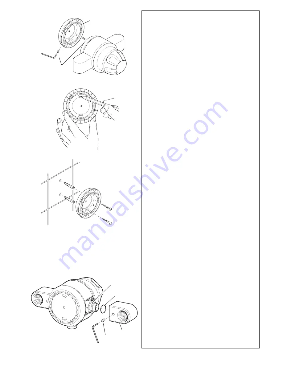
Backplate
Grub
Screws
2.
Remove the backplate by releasing,
anticlockwise, the two recessed grub
screws which retain the backplate
against the brass shower control body,
using the 2.5 mm A/F hexagon wrench
(supplied).
3.
Mark the final position of the shower
control on the finished wall surface
using the backplate as a template.
Mark the position of the two holes on the
backplate. Ensure the holes are
vertically aligned.
WARNING!
Ensure there are no buried
cables or pipes in the wall before drilling.
4.
Drill the two marked fixing holes and fit
the wallplugs provided. Secure the
backplate to the wall with the two No. 8
x 1
3
/
4
"
fixing screws.
Note!
Screws with larger heads will foul
the shower control body.
5. Thoroughly flush the incoming hot
and cold water supplies before
connecting the shower control
.
6.
Release, anticlockwise, the two grub
screws that retain the inlet elbows,
using the 2.5 mm A/F hexagon wrench
(supplied).
Ensure that the ‘O’ seal is
correctly located on the smaller
diameter shoulder of the brass inlet
connector, and not in the ‘V’ groove.
'V' Groove
'O' Seal
Inlet
Elbow
Grub
Screw
Summary of Contents for Combiforce 415
Page 51: ...51 Appendix Notes ...


