14
13.
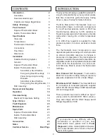
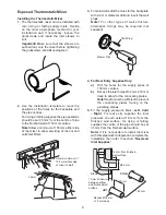
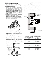
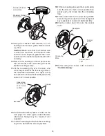
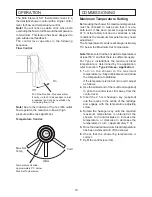
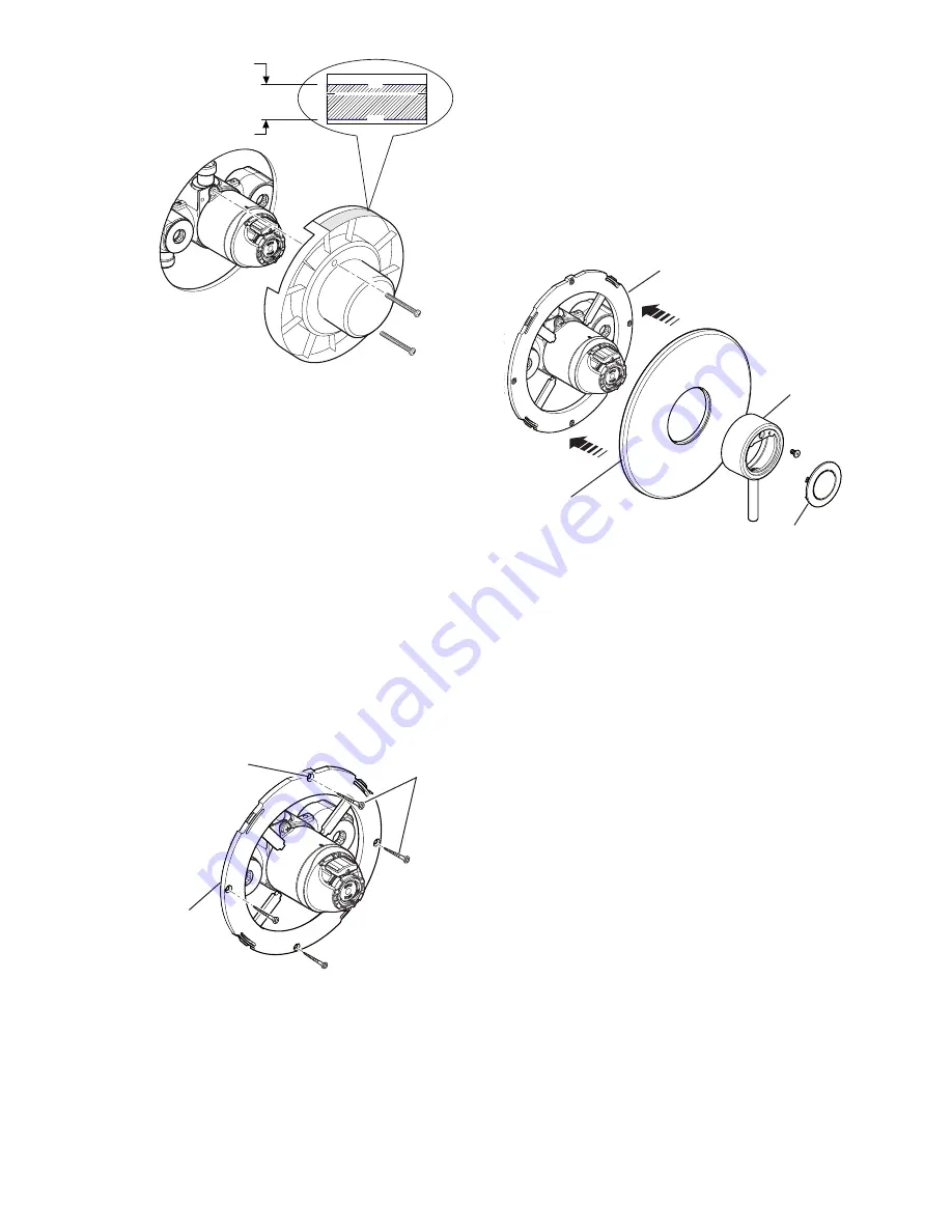
Using the ‘Finished Wall Indicator’ on the
building-in shroud as a guide, finish the wall,
e.g. tiles.
Caution!
Make sure that the finished wall
is within the maximum and minimum limits
and to an even depth (no greater than 2 mm
variation) or the control components will not fit
correctly.
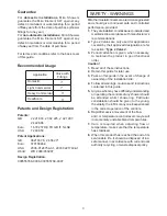
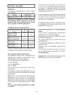
14.
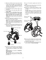
Remove the building-in shroud and secure
the chrome trim to the mixer using two of the
bracket securing screws.
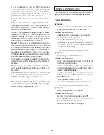
15
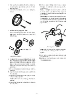
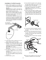
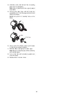
. Fit the concealing ring over the mixer and
mark the positions of the four fixing holes in
the orientation illustrated. The upper screw
hole should be located horizontally above the
valve in 12 ‘o’clock position.
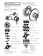
16.
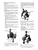
For solid walls drill four Ø6 mm holes for the
wall plugs. For other types of wall structure
alternative fixings may be required (not
supplied).
17.
Insert the wall plugs and attach the concealing
ring to the wall with the screws provided.
F13125
Finished Wall
Min
Max
Minimum finished
wall surface
Maximum finished
wall surface
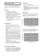
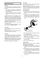
Control Lever
Trim
Control
Lever
Backplate
Concealing
Plate
18.
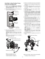
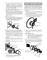
Fit the concealing plate over the mixer making
sure the slot is in the 6 o’clock position then
gently push until it clips onto the concealing
ring.
19.
Fit the control lever to the mixer using the M4
x 8 securing screw, use the 2.5 mm hexagonal
key (supplied) to ensure it is tightened fully.
20.
Clip the control lever trim onto the control
lever.
21.
Before using the shower, refer to section:
‘Commissioning’
.
Screws
Backplate
Upper screw
hole must be
at 12 o’clock
position
Summary of Contents for Element SLT
Page 27: ...27 NOTES...


