background image


8B 

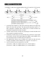
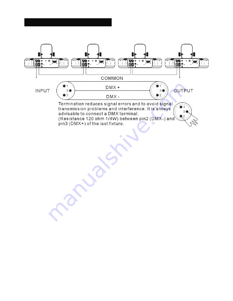
  6. DMX512 Connections   

The DMX512 is widely used in intelligent lighting control, with a maximum of 512 channels. 


1. 

Connect the fixture together in a “daisy chain” by XLR plug cable from the output of the 

fixture to the input of the next fixture. The cable cannot be branched or split to a “Y” 

cable.  Inadequate  or  damaged  cables,  soldered  joints  or  corroded  connectors  can 

easily distort the signal and shut down the system 

2.  The  DMX  output  and  input  connectors  are  pass-through  to  maintain  the  DMX  circuit 

when no power is connected to the fixture. 

3.  At last fixture, the DMX cable has to be terminated with a terminator to reduce signal 

errors. Solder a 120-ohm 1/4W resistor between pin 2(DMX-) and pin 3(DMX+) into a 

3-pin XLR-plug and plug it in the DMX-output of the last fixture. 

4.  Each  lighting  fixture  needs  to  have  an  address  set  to  receive  the  data  sent  by  the 

controller. The address number is between 0-511 (usually 0 & 1 are equal to 1). 

5.  3 pin XLR connectors are more popular than 5 pins XLR. 

3 pin XLR: Pin 1: GND, Pin 2: Negative signal (-), Pin 3: Positive signal (+)   

5 pin XLR: Pin 1: GND, Pin 2: Negative signal (-), Pin 3: Positive signal (+) 


Summary of Contents for LED-747

Page 1: ...MIRACLED LED 747 User Manual Please read the instructions carefully before use ...

Page 2: ...1B TABLE OF CONTENTS 1 Safety Instructions 2 Technical Specifications 3 Main Function 4 How to control the fixture 5 DMX 512 Configuration 6 DMX 512 Connections 7 Troubleshooting 8 Fixture Cleaning ...

Page 3: ...ately Never try to repair the fixture by yourself Repairs carried out by unskilled people can lead to damage or malfunction Please contact the nearest authorized technical assistance center Always use the same type spare parts Do not connect the device to any dimmer pack Do not touch any wire during operation and there might be a hazard of electric shock To prevent or reduce the risk of electrical...

Page 4: ...ern Strobe Chase Speed Ch4 Ch7 Dimmer Power supply Input Voltage AC 100 250V 50 60Hz Power consumption 30W LED Total 224pcs Red 80pcs Green 60pcs Blue 48pcs White 36pcs Dimension 473mm x 279mm x 103mm Weight 5KG 3 Main Function To select any functions press MENU button until the required one is shown on the display Select the function by ENTER button and the display will blink Use DOWN and UP butt...

Page 5: ...play will blink Use DOWN and UP button to select the 4 channel or 7 Channel mode Once the mode has been selected press the ENTER button to setup or automatically return to the main functions without any change after 10 seconds To go back to the functions without any change press the MENU button again Master Mode Press the MENU button up to when the is shown on the display Pressing ENTER button Use...

Page 6: ...on the display Pressing ENTER button Once the mode has been selected press ENTER button to setup or automatically return to the main functions without any change after 10 seconds Back to the functions without any change press MENU button again Fixture Hours Press the MENU button up to when the is blinking on the display Pressing ENTER button and the display will show the number of working hours of...

Page 7: ...D will be constantly on and sound LED will flash to the music The other units will have to set in slave mode and select normal or 2 light show mode Their DMX cables plugged into the DMX input jacks daisy chain and the slave led lights will constantly on 2 light show In slave mode means the unit works normally and means 2 light show In order to create a great light show you can set on the second un...

Page 8: ... change the DMX512 address Once the address has been selected press and keep ENTER button pressed up to when the display stops blinking or storing automatically 8 seconds later To go back to the functions without any change press the MENU button again If you use please refer to the following diagram to address your DMX512 channel for the first 4 units DMX address can be setting remotely by IL 0824...

Page 9: ...re pass through to maintain the DMX circuit when no power is connected to the fixture 3 At last fixture the DMX cable has to be terminated with a terminator to reduce signal errors Solder a 120 ohm 1 4W resistor between pin 2 DMX and pin 3 DMX into a 3 pin XLR plug and plug it in the DMX output of the last fixture 4 Each lighting fixture needs to have an address set to receive the data sent by the...

Page 10: ... on connectors or on PCB of the fixture or the previous one 4 Try to use another DMX controller 5 Check if the DMX cables run near or run alongside to high voltage cables that may cause damage or interference to DMX interface circuit C Some fixtures don t respond to the easy controller 1 You may have a break in the DMX cabling Check the LED for the response of the master slave mode signal 2 Wrong ...

Page 11: ...e environment in which the fixture operates damp smoky or particularly dirty surrounding can cause greater accumulation of dirt on the fixture s optics Clean with soft cloth using normal glass cleaning fluid Always dry the parts carefully Clean the external optics at least every 20 days Clean the internal optics at least every 30 60 days ...

Page 12: ... CE mark in accordance with the provision of the Electromagnetic Compatibility EMC Directive 89 336 EEC EN55014 2 1997 A1 2001 EN61000 4 2 1995 EN61000 4 3 2002 EN61000 4 4 1995 EN61000 4 5 1995 EN61000 4 6 1996 EN61000 4 11 1994 Harmonized Standard EN60598 1 2000 ALL 2000 A12 2002 Safety of household and similar electrical appliances Part 1 General requirements ...

Reviews: