GUIDE TO INSTALLATION AND OPERATION
10
| HMP-1801
DRP
3SRP
2OUT-3SRP
(Densité 2)
(Densité 3) (Densité 3)
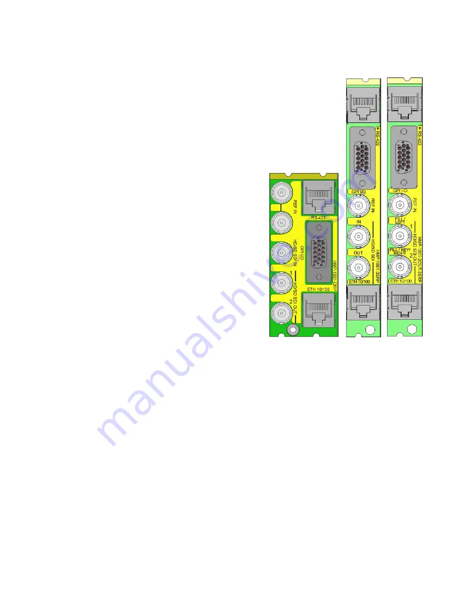
Figure 2.1 Rear Panel Connectors
2.4 Rear Connector Panels
The HMP-1801 requires a dual-slot rear in the Densité 2 frame, and
a single-slot or dual-slot rear in the Densité 3 frame:
DRP (2RU)
•
One reference input and one loop
•
One video input for video recording
•
Two video outputs
•
One HD15 connector for GPI I/O lines (6 in / 6 out)
(Miranda’s NSH-15M wiring terminal adapter can be used to
connect the GPI lines to this connector)
•
One RJ-45 for media transfer over Ethernet
•
One RJ-45 (RS422) for control over VDCP protocol
3SRP (3RU)
•
One reference input
•
One video input for video recording
•
One video outputs
•
One HD15 connector for GPI I/O lines (6 in / 6 out)
•
One RJ-45 for media transfer over Ethernet
•
One RJ-45 (RS422) for control over VDCP protocol
2OUT-3SRP (3RU)
•
One reference input
•
Two video outputs
•
One HD15 connector for GPI I/O lines (6 in / 6 out)
•
One RJ-45 for media transfer over Ethernet
•
One RJ-45 (RS422) for control over VDCP protocol
With the double-width rear panel installed in a Densité-2 frame, the
HMP-1801 must be installed in the right-most of the two slots
covered by the panel in order to mate with the panel’s connectors.
If it is placed in the wrong slot, the front panel LED will flash red.
Move the card to other slot for correct operation. No damage will result to the card if this occurs.
2.4.1 Ethernet Port Configuration
The ethernet port must be configured before it can be used to download media into the HMP-1801.
•
Using iControl: See section 3.4.3.1 for instructions.
•
Using the local control panel: See section 3.3 for instructions and use the menu found in the Annex on page 67.
In order to communicate with the HMP-1801, the following network ports should be opened:
•
HTTP:
80
•
FTP:
20 and 21
•
Control:
5200 and 5201


