GUIDE TO INSTALLATION AND OPERATION
2
| HMP-1801
1.3
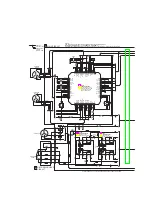
Block Diagram
This block diagram shows the functionality of the HMP-1801.
Figure 1.1 Functional block diagram of the HMP-1801
1.4 Front Card-edge Interface
The front card-edge of the HMP-1801 incorporates four elements:
•
Status LED (see section 3.2)
•
Select Button (see section 3.3)
•
Compact Flash status indicator
•
Ethernet Status indicator
S
el
ec
t
S
ta
tu
s
HMP-1801
Status LED
Select Button
Compact Flash Status
Ethernet Status
Figure 1.2 Front card-edge layout


