270
Routers & Kaleido-X
12
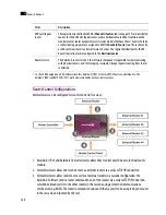
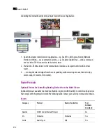
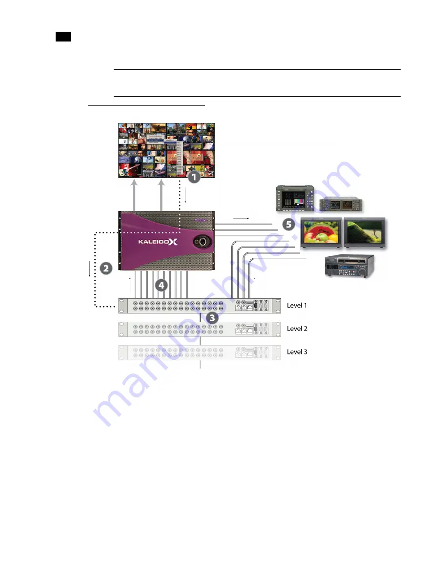
Controlling External Routers in a Cascade
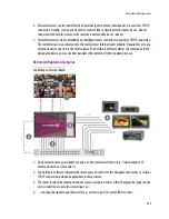
1. An operator chooses an assignment option on the monitor wall menu (e.g. “switch output 23 of
external router A, Level 2 to QC monitor”).
2. The Kaleido-X Software interprets the command, and sends it to the designated router over a serial or
TCP/IP connection, using the appropriate router protocol.
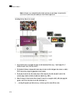
3. The physical router receives the command, and then relays it to the other physical routers in the
cascade using an internal communications mechanism (e.g. MIDI).
4. When the targeted
Level
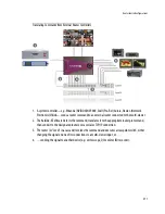
receives the command, it executes a crosspoint switch, either changing the
signal on one of its connections to a multi-viewer input, or…
5. …sending the signal to another device (e.g. vector scope, QC monitor, ISO recorder).
Note:
In the same way, commands from the monitor wall menu can also change crosspoints on the
multi-viewer’s internal router (if available) or on the
KX Router
logical router.
Summary of Contents for Kaleido-X
Page 1: ...Kaleido X User s Manual Part Number M770 2800 111 1 June 2011 ...
Page 8: ...viii toc ...
Page 33: ...Loading a Layout 25 Kaleido X16 ...
Page 34: ...26 Getting Started 2 Kaleido X 4RU ...
Page 152: ...144 Creating Logical Sources 7 ...
Page 178: ...170 Setting Up Rooms 8 ...
Page 244: ...236 Creating Layouts 9 ...
Page 253: ...Detailed Directions 245 3 Under Properties General type a Friendly name for the Action ...
Page 256: ...248 Creating Actions 10 ...
Page 272: ...264 Managing Kaleido RCP2 Users 11 ...
Page 348: ...340 Tally Interface Devices 13 ...
Page 350: ......
Page 352: ...344 Using the Serial to TCP IP Dispatcher 15 ...
Page 406: ...398 Index ...

