Configuring a Router Controller
297
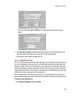
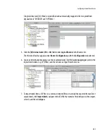
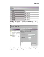
5. In the
Interconnects
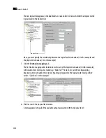
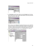
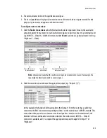
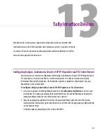
tab, click the router controller icon. Under the
Properties
tab, a list of settings
appears, with default values for the serial communication parameters: the bit rate (bps), the number
of data bits, parity, stop bits and flow control:
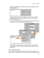
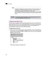
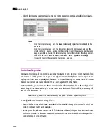
However, in this case, there is no
Router
box for specifying which logical router is to be controlled. This
is because the SW-P-08 protocol allows the controller to pass the identifier for the logical router with
a command (i.e. it tells the multi-viewer to make a crosspoint change for logical router X). The ID that
it passes is the logical router matrix ID (refer to “Step 3 – Adding Logical Routers” on page 285).
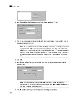
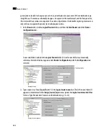
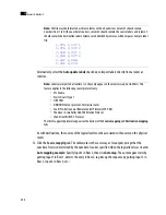
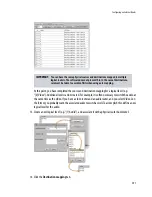
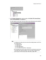
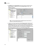
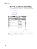
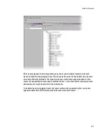
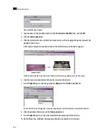
6. Click the
Router Configurations
tab to view (or set) the logical matrix ID:
Summary of Contents for Kaleido-X
Page 1: ...Kaleido X User s Manual Part Number M770 2800 111 1 June 2011 ...
Page 8: ...viii toc ...
Page 33: ...Loading a Layout 25 Kaleido X16 ...
Page 34: ...26 Getting Started 2 Kaleido X 4RU ...
Page 152: ...144 Creating Logical Sources 7 ...
Page 178: ...170 Setting Up Rooms 8 ...
Page 244: ...236 Creating Layouts 9 ...
Page 253: ...Detailed Directions 245 3 Under Properties General type a Friendly name for the Action ...
Page 256: ...248 Creating Actions 10 ...
Page 272: ...264 Managing Kaleido RCP2 Users 11 ...
Page 348: ...340 Tally Interface Devices 13 ...
Page 350: ......
Page 352: ...344 Using the Serial to TCP IP Dispatcher 15 ...
Page 406: ...398 Index ...

