Key Concepts
33
Time code monitor
A
time code monitor
displays the Ancillary Time Code (ATC) from an HD video signal, or the
time code found in an embedded SDI video signal, part of the vertical interval of an analog
signal (VITC), or other external Linear Time Code (LTC). Time code monitors can be used for
monitoring the duration of programs.
Timer
A
timer monitor
is based on a
timer
defined within the Kaleido-X system.
Three timer modes are available: (1) UP: timer counts up starting from zero up to a preset
time, (2) DOWN: timer counts down from a preset time to zero, and (3) REMAINING: timer
counts down from the current time until it reaches a preset time.
Timers are defined and configured in XEdit. They can be slaved to production timers,
assigned to logical sources, assigned to rooms or specific RCP users, and controlled from
the Kaleido-RCP2. See “Using Timers” on page 53.
Clock
A
clock
is the visual representation of time in a video or display. It can be based on a
reference LTC signal or on the Kaleido-X system time. Clocks can be in a digital or analog
format.
Note:
The KMV-3901/3911 supports digital clocks only.
Action
An
action
is an operation automatically performed in response to a specific trigger.
Monitor
wall actions
are directly associated with layout elements.
Background (floating) actions
are
actions that are global to the Kaleido-X system. Unlike monitor wall actions, background
actions are always available. See “Triggering Actions” on page 56.
Trigger
A
trigger
is an event that triggers an action. An example of a trigger could be a double click
on a monitor. Background actions are triggered by alarms or by Gateway commands. In
XEdit, when defining an action for a layout element, you could specify, for instance, that a
specific full screen layout be displayed on the monitor wall in response to the trigger.
Alarm monitor
Alarm monitors
help you see the status of global and virtual alarms, but their use is not
limited to this type of alarms. When any alarm level is assigned to an alarm monitor, the
status of this alarm will be shown. When using the global alarm at the text label level, it
will display the text value of the alarm, which is a readable name. See “Configuring Alarm
Monitors” on page 216.
Alarm latch
To prevent operators from missing temporary alarms on the monitor wall, layout elements
that are capable of displaying an alarm status (e.g. video monitors, UMDs, alarm monitors)
can be configured with a latching mechanism. An
alarm latch
will keep the error state
visible until someone acknowledges the associated alarm.
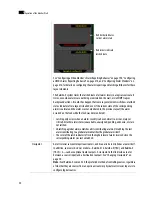
Video monitors can provide alarm status information through their borders’ color and
blinking behavior, and show the latched state as small indicators in each corner of the
video window. UMDs (text and tallies) and alarm monitors can change their text or
background color and blinking behavior, to reflect the alarm status and show the latched
state through their borders.
Summary of Contents for Kaleido-X
Page 1: ...Kaleido X User s Manual Part Number M770 2800 111 1 June 2011 ...
Page 8: ...viii toc ...
Page 33: ...Loading a Layout 25 Kaleido X16 ...
Page 34: ...26 Getting Started 2 Kaleido X 4RU ...
Page 152: ...144 Creating Logical Sources 7 ...
Page 178: ...170 Setting Up Rooms 8 ...
Page 244: ...236 Creating Layouts 9 ...
Page 253: ...Detailed Directions 245 3 Under Properties General type a Friendly name for the Action ...
Page 256: ...248 Creating Actions 10 ...
Page 272: ...264 Managing Kaleido RCP2 Users 11 ...
Page 348: ...340 Tally Interface Devices 13 ...
Page 350: ......
Page 352: ...344 Using the Serial to TCP IP Dispatcher 15 ...
Page 406: ...398 Index ...

