background image

Using XEdit Online

69

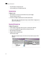
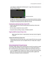
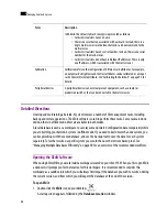
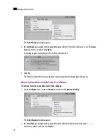
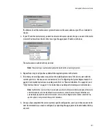
To customize the layout of the XEdit application window:

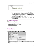
• Resize the window, and its three panes, by dragging the window’s borders, corners, and pane splitters.

• Move the 

Tips

Tools

, and 

Properties

 tabs between the left and right panes, and reorder them, by 

clicking their handle and dragging to the desired location.

• Close  the 

Tips

Tools

, and 

Properties

 tabs by clicking their X button.

• Undock  the 

Tips

Tools

, and 

Properties

 tabs from the main window, by clicking their square button.

• Dock  the 

Tips

Tools

, and 

Properties

 tabs, by clicking their 

X

 button.

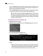
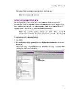
To restore the default application layout:

1. Dock the 

Tips

Tools

, and 

Properties

 tabs, if they are undocked, by clicking their 

X

 button.

2. On the 

View

 menu, point to 

Panes and tabs

, and then click 

Restore default window settings

.

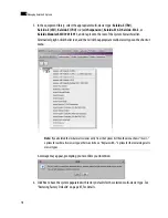
To close XEdit:

On  the 

File

 menu, click 

Exit

. Alternatively, click the 

×

 button in the upper right corner of the main 

application window.

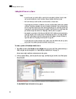
Using XEdit Online

When using XEdit in 

online

 mode, any changes made are applied and stored directly on the multi-viewer. 

When using XEdit in 

offline

 mode, all changes are stored locally on the user’s PC, and the database must be 

exported to the multi-viewer for the changes to take effect.

When connected to a multi-viewer, any change you make to your system’s configuration takes effect 
immediately 

on the multi-viewer

 itself; your local database is not involved. The online mode is not limited 

to basic system configuration; changes can also be made to existing logical sources, rooms, layouts, RCP 
users, etc.

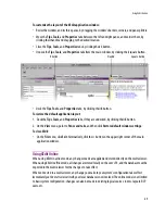
X button

Handle

Square button

Splitter

Summary of Contents for Kaleido-X

Page 1: ...Kaleido X User s Manual Part Number M770 2800 111 1 June 2011 ...

Page 2: ...ans electronic or mechanical including photocopying and recording for any purpose unless specifically authorized in writing by Miranda Technologies Inc AMirandaTechnologiesInc manualmayhavebeenrevisedtoreflectchangesmadetotheproductduring itsmanufacturinglife Thus differentversionsofamanualmayexistforanygivenproduct Careshouldbe taken to ensure that one obtains the proper manual version for a spec...

Page 3: ...eido X 7RU x 2 Expansion 12 Kaleido X Cluster 13 KMV 3901 3911 Cascade 14 Detailed Directions 14 Verifying your System Configuration 15 Loading a Layout 22 Cabling Diagrams 24 RS 422 Connection Diagram 28 XEdit Application Shortcuts 29 3 Operation of the Monitor Wall 31 Key Concepts 31 Detailed Directions 35 Logging on to the Monitor Wall Using the Kaleido RCP2 35 Displaying the Dashboard 36 Hidin...

Page 4: ...the Monitor Wall 61 4 Managing Kaleido X Systems 63 Key Concepts 63 Detailed Directions 66 Opening the XEdit Software 66 Using XEdit Online 69 Importing a Database 71 Exporting a Database 73 Creating a Backup 74 Retrieving a Backup 75 Creating a Single Multi Viewer System 77 Creating a Cluster 79 Configuring the System Representation 85 Restoring Factory Defaults 87 Managing Multiple Databases Eff...

Page 5: ...Creating and Configuring Logical Sources 136 Configuring Alarm Levels 141 Monitoring Internal Router Outputs on the Monitor Wall Sample Scenario 142 8 Setting Up Rooms 145 Key Concepts 145 Detailed Directions 146 Managing Rooms 146 Configuring Displays 152 Managing Display Libraries 166 9 Creating Layouts 171 Key Concepts 171 Detailed Directions 173 Managing Layouts 173 Configuring Video Monitors ...

Page 6: ...om Access 251 Setting Room Preferences 252 Setting RCP User Preferences 256 12 Routers Kaleido X 265 Overview 265 Internal Router 266 Kaleido X as a Router 266 Key Concepts 267 Router Control Configurations 268 Router Protocols 272 Serial Connections 275 Q A 277 Detailed Directions 279 Configuring an External Router 279 Configuring a Router Controller 292 Configuring Internal Router Cards 298 Rout...

Page 7: ... 16 Administration and Servicing 345 Key Concepts 345 Default IP Settings 346 Hardware and Software Options 347 Dashboard Messages 349 Network Considerations Port Usage 353 Detailed Directions 358 Assigning an IP Address to Each Device in Your System 358 Enabling Options 371 Configuring Power Supply Redundancy on a Kaleido X16 373 Installing XEdit 375 Obtaining EDID Data From Display Screens When ...

Page 8: ...viii toc ...

Page 9: ... SDImonitoringoutputs withembeddedaudio oneassociatedwithHead1 andonewith Head 2 See KMV 3901 3911 on page 348 for the list of optional features and Configuring the HD SDI Monitoring Output Format on page 161 for more information Enhancements in Kaleido X Version 5 30 Teletext subtitling color Text color attributes are now supported for teletext WST OP 47 See Setting a Video Monitor s Text Mode on...

Page 10: ...nitoring output through HDMI The Kaleido X16 and KMV 3901 8x2 now support audio monitoring output over HDMI for PCM audio pairs from SDI sources Support for Cascade solution To address solutions with more inputs per head using smaller cost effective multi viewers KMV 3901 8x2 multi viewers can now be configured in cascade This allows the support of the following configurations KMV 3901 8x2 cascade...

Page 11: ...homepage Itopensas a standalone panel updated in real time as multi viewer inputs are assigned different router sources and crosspoints are changed on the upstream router For each multi viewer input the panel displays the current router source assignment the corresponding router destination as well as router status information In the case of a Kaleido X multi viewer model it also indicates if an i...

Page 12: ...utputcalibrationsandothersettingscanbeconfiguredinXEdit Inthecaseof the Kaleido X multi viewer models the presence and status normal mode safe mode of the KXO HDM mezzanine are available via SNMP Traps are also available for both alarms Note Like other card presence alarms the KXO HDM traps are not configurable and are always sent ...

Page 13: ...l of the Kaleido X SoftwareandXEditapplicationforcontrollingandmonitoringaudio andvideobroadcastsignalpathsfor interfacing routing distribution and other peripheral devices The Kaleido X series hardware including the Kaleido Modular Kaleido X16 and Kaleido X multi viewer models and the associated software products are designed and produced by Miranda Technologies Inc For installation instructions ...

Page 14: ...aleido X 7RU x2 Expansion 12 Kaleido X Cluster 13 KMV 3901 3911 Cascade 14 Kaleido Modular The Kaleido Modular KMV 3911 which has replaced the earlier KMV 3901 model is an expandable 8 input dual output multi viewer 3Gbps HD SD on one Densité Series card Hosted in a Densité 3 frame the KMV 3911 is the most space and energy efficient multi viewer system with up to 20 multi viewer outputs per 3 RU f...

Page 15: ... auto sensing 3Gbps HD SD video inputs two independent HDMI outputs Video signals can be repeated in up to eight windows and scaled up to 1920 1200 pixels Audio signal video time code and AFD WSS data can be extracted for on screen display A reference signal from a REF 1801 Densité card can be used to minimize processing delay and reference clocks on the monitor wall Expansion through combination ...

Page 16: ...It offers the highest level of image quality and can be used with 3Gbps HD SD and Analog video It is ideal for small control rooms although it can also be paired with routers to create the very largest combined multi viewer and routing systems There are two types of Kaleido X16 Kaleido X16 S single head and Kaleido X16 D dual head ...

Page 17: ...lycases aswellascommunitytelevision TheKaleido X16 s super silent design is highly appreciated for use within studios and control rooms Kaleido X16 provides a subset of the features of the Kaleido X 4RU and 7RU models 1RU non modular frame 16 auto sensing 3Gbps HD SD Analog video inputs two independent HDMI outputs Two 3Gbps HD SD router outputs 3Gbps with 3D support SMPTE 425M Level A B ...

Page 18: ...2andadvancedRCP 200withrouter control Internal router control by NVISION control panel and NV9000 Controller Super silent for installation within studios and control rooms Kaleido X 4RU The Kaleido X 4RU is a multi room multi image display processor and router in a single expandable chassis Its unique mix of capabilities represents the most integrated monitoring and routing solution As a multi ima...

Page 19: ...ts the most integrated monitoring and routing solution As a multi image processor it offers the highest level of signal flexibility Each chassis can display 96 HD SD orAnaloginputsanynumberoftimes inanysize across8displaysofanyresolutionandorientation Asa router it offers switching of 96 unprocessed inputs to 48 HD SD outputs for feeding monitors test equipment and master control or production swi...

Page 20: ...eachwithitsownexpansion KXO EXP card areconnectedbyahighbandwidthcable suchthatalltheoutput KXO modulesoneachframe up to 6 in total have access to all inputs KXI on each frame up to 192 in total without any blocking or bandwidth limitations Using XEdit the two frames can be configured as a single system allowing rooms to share input modules from either frame The expansion card allows seamless shar...

Page 21: ...ription InstallationManual for more information Kaleido X 7RU 2expansionsystemoverview Kaleido X Cluster Asofversion4 00oftheKaleido XSoftware itispossibletoconfigureaclustersystem allowingoperation of layouts sharing output signals from multiple Kaleido X multi viewers fed by a router while using only one mouse and one Kaleido RCP2 Refer to Creating a Cluster on page 79 for more information ...

Page 22: ...viewersasacascadesystem Unlike the cluster whose purposeistoincreasethenumberofoutputheads in a room the cascade increases the maximum number of inputs that can be displayed to a single head Formoreinformation refertotheKMV 3901 3911CascadeStep by StepConfigurationguide availableon the Kaleido X DVD Detailed Directions Verifying your System Configuration 15 Loading a Layout 22 ...

Page 23: ...ntPCtostarttheXAdminapplication see InstallingXEdit onpage375 On the Configure menu click Use XAdmin This will open your default Web browser Method2 From a workstation on the same subnet open a Web browser window and type the multi viewer s IP address in the address bar 1 The Kaleido X home page appears 2 Click the XAdmin button The XAdmin Status and Options page appears displaying a list of all m...

Page 24: ...ulti viewer theheadingrowsshowthecardtype serialnumber firmware and safemode versions a card status indicator and input signal status indicators The card status indicator shows whether the card is running normally green or in safe mode red The signal status indicators reveals the presence of a valid input signal at the corresponding connector Card type Serial number Version information Input signa...

Page 25: ...tcardbuttonattheendofacard sheaderrow to reset the card remotely directly from your Web browser InthecaseofaKaleido X16orKaleido Modularmulti viewermodel clicktheResetmulti viewer buttonattheendofthemulti viewer sheaderrowtoresetthemulti viewerremotely directlyfrom your Web browser 5 Review the enabled options for each module and make sure that no error is reported Expand details Refresh Reset car...

Page 26: ...18 Getting Started 2 Note See HardwareandSoftwareOptions onpage 347formoreinformationontheoptionsavailable for the different multi viewer models ...

Page 27: ...s Theotherstatuses especiallytheoneslistedinthetablebelow shouldallbenormal althoughif youleftthedooropenwhencheckingaGPI Genlockcard sLEDs youmayseeawarningunderChassis Door Open Status 1 The KXA GPI GEN card with support for GPI is standard on the Kaleido X 7RU and optional for the Kaleido X 4RU GPI support is built in on the Kaleido X16 and Kaleido Modular multi viewers KXA GPI GEN 1 2V Status ...

Page 28: ...GEN 48V Power Supply A Fuse Status KXA GPI GEN 48V Power Supply B Fuse Status KXA GPI GEN Board High Temperature KXA GPI GEN Chassis Door Open Status KXA GPI GEN Power Supply A Status KXA GPI GEN Power Supply B Status KXA GPI GEN Rear Fan 1 Status KXA GPI GEN Rear Fan 2 Status KXA GPI GEN Rear Fan 3 Status KXA GPI GEN Rear Fan 4 Status KXA GPI GEN Rear Fan 5 Status KXA GPI GEN Rear Fan 6 Status ...

Page 29: ...e g load layout presets Verifying an Audio Bridge Terminal To verify that the ABT is functioning normally Inspect the ACTIVITY and front panel LEDs on the unit to make sure there are no error conditions The ACTIVITY indicator is located on the right hand side of the rear panel This LED reports the status of the Ethernet connection as follows Color Board Status Off No link detected Green Normal goo...

Page 30: ...gned to this room Please load a layout To load a layout on the monitor wall 1 Connect a mouse to the Kaleido RCP2 if available and log on to the multi viewer from the RCP2 if you have not already done so see Logging on to the Kaleido RCP2 on page 368 Alternatively connect the mouse directly to one of the USB ports on the multi viewer 2 Right clickanywhereonthemonitorwall pointtoMonitorWall ifyoucl...

Page 31: ...d appear on the room displays Example ofa defaultlayout showing16videostreams Note Bydefault eachroomisassociatedwithonemulti vieweroutputoroutputcard Mostpredefined layoutsareconfiguredtoshowallvideostreamsforagiveninputcard inthecaseoftheKaleido Xmulti viewer models or all video streams connected to the multi viewer sinputs in the case of a Kaleido X16 or Kaleido Modular multi viewer model ...

Page 32: ...24 Getting Started 2 Cabling Diagrams KMV 3901 3911 Note Youcanalsousethe10LAYOUTPRESETSbuttonsontheRCP2toloadtheassociateddefaultlayout to the monitor wall ...

Page 33: ...Loading a Layout 25 Kaleido X16 ...

Page 34: ...26 Getting Started 2 Kaleido X 4RU ...

Page 35: ...Loading a Layout 27 Kaleido X 7RU Kaleido X 7RU x 2 Refer to the Kaleido X 7RU Expansion chapter in the Kaleido X 7RU Hardware Description Installation Manual ...

Page 36: ...CS Note For information on the KMV 3911 multi viewer s RS 422 interface refer to the KMV 3911Guide toInstallationandOperation available on the DVD that shipped with your system Note The RS 422 ports each have an RJ 45 connector in order to preserve space on a busy panel The RS 422 interface specifies a DE 9 connector so if you are using this interface you will require a DE 9 to RJ 45 adapter Miran...

Page 37: ...ctory resolutions Ctrl Shift E Restore the factory audio scales Ctrl Shift A Restore the factory calibrations Ctrl Shift C Restore the factory widget libraries Ctrl Shift L Toggle the grid Ctrl Shift G Toggle the Tips pane Ctrl Shift H Toggle the Properties pane Ctrl Shift P Toggle the layout navigator Ctrl Shift N Toggle the status bar Ctrl Shift S Toggle the Tools pane Ctrl Shift T Cut Ctrl X Co...

Page 38: ...30 Getting Started 2 Redo last operation Ctrl Y Undo last operation Ctrl Z Unlock composite F2 Zoom in Ctrl plus sign Zoom out Ctrl minus sign Action Shortcut Key ...

Page 39: ...to the Monitor Wall Using the Kaleido RCP2 on page 35 Automatic resolution detection Automaticresolution detection eases the initial setup of a new display monitor by automaticallydeterminingthebestresolutionsupportedbythedisplay Thisensuresthat the multi viewer will be configured for the best video quality When a new display is connected the multi viewer will detect the EDID of the display on boo...

Page 40: ...data sources and text attributes A logical source can be used as a whole and assigned to a virtual monitor See Assigning Sources to Monitors on page 48 Video monitor A video monitor is a layout element used to define an area for displaying a video signal Within a video monitor the video window is the active area where the video signal is displayed Composite monitor A compositemonitor also referred...

Page 41: ...itor wall actions background actions are always available See Triggering Actions on page 56 Trigger Atriggerisaneventthattriggersanaction Anexampleofatriggercouldbeadoubleclick on a monitor Background actions are triggered by alarms or by Gateway commands In XEdit whendefininganactionforalayoutelement youcouldspecify forinstance thata specific full screen layout be displayed on the monitor wall in...

Page 42: ...larm severity is above normal i e minor major or critical All other alarm states unavailable unassigned pending unknown etc are not latched Unlatching a global alarm unlatches all its contributing alarms Unlatching the last alarm contributing to a global alarm unlatches the global alarm itself The color of the latch indicator reflects the highest level of alarm received since the corresponding ala...

Page 43: ... The rooms are listed in the form multi viewer name room name If a room belongs to a cluster system its name appears once for each of the member multi viewers e g if two multi viewers KX1 andKX2 areconfiguredasacluster andROOM1includesdisplaysfedbybothmulti viewers thenboth KX1 ROOM1 and KX2 ROOM1 will be listed You may select either one 3 Intheroomlist selecttheroomyouwishtoaccessbypressingthe2ke...

Page 44: ... IP address software version and current error messages In such cases you must close the dashboard manually To display the dashboard 1 Right clickanywhereonamonitor Ontheshortcutmenu pointtoMonitorWall andthenclickShow dashboard to display the dashboard associated with the current head Note By default the user name Admin has no password Notes If at any time the message Target system is offline or ...

Page 45: ... the Dashboard To hide the dashboard Clickthe buttonatthebottom rightcornerofthedashboard Alternatively right clickanywhereon the monitor wall point to Monitor Wall on the shortcut menu if you clicked a layout element and then click Hide dashboard to hide the dashboard on the current display Note If you right click the monitor wall background directly then the monitor wall shortcut menu appears im...

Page 46: ...g the Mouse To load a layout on the monitor wall by using the mouse 1 Right clicktheanywhereonthemonitorwall pointtoMonitorWall ifyouclickedalayoutelement and then click Load layout on the shortcut menu Note Clicking the button closes the dashboards on every display monitor in the room if they were displayed automatically Note Whenadashboardisclosedwhilethesystemisinanerrorcondition itwillautomati...

Page 47: ...ish to load from the set of layouts defined for this room and then click OK The new layout appears on the monitor wall Loading a Layout by Using the RCP2 To load a layout on the monitor wall by using the RCP2 1 Press LOAD on the RCP2 The layout chooser appears Load layout ...

Page 48: ...atedwiththepresetbuttonforthecurrentuserwillbeloadedontothemonitorwall See Assigning Room Layouts to an RCP User s Presets on page 280 for more details Refreshing a Layout To refresh a layout Right clickanywhereonthemonitorwall pointtoMonitorWall ifyouclickedalayoutelement and then click Refresh on the shortcut menu Locating the Mouse Pointer on the Monitor Wall If you have a cluster system the mo...

Page 49: ...ne and then press FULL SCREEN again on the RCP2 Changing a Source s Aspect Ratio To change the aspect ratio using the RCP2 Movethepointeroverthevideosourcewhoseaspectratioyouwishtochange andthenpressASPECT RATIO on the RCP2 Continue pressing ASPECT RATIO to toggle between the available aspect ratio options 4 3 16 9 andpossiblyathirdcustomaspectratioifonewasdefinedinXEditforthemonitor To change the...

Page 50: ...2 ContinuepressingUNDERSCANtotoggle between underscan and overscan mode To toggle the cropping mode using the mouse Right click the video source If the video is in underscan mode then the shortcut menu will allow you to change to overscan If the video is in overscan mode then the shortcut menu will allow you to change to underscan Note There may be one more choice on the menu if you set a custom a...

Page 51: ...eo source and then click Safe Area on the shortcut menu The safe area markers appear inside the video window 2 Click Safe Area again on the shortcut menu to hide the markers Notes The overscan margins are set to 5 by default They can be customized in XEdit In the case of a KMV 3901 3911 multi viewer up to 10 cropping is supported Safetitleareaandaspectratiomarkersfollowthevideosignal e g ifthesafe...

Page 52: ...event the shortcut menu from being too crowded by CC 608 CC 708 and Teletext Subtitling options itscontent label iconandavailablechoice changes dependingonthecurrentvideoformat Note The KMV 3901 3911 multi viewers do not support displaying of subtitles and closed captions Signal type Text Mode Icon Label Available choices SD SDI CVBS 525 Auto CC 608 CC 608 Off CC1 Text mode sub menu Any CC 608 SD ...

Page 53: ...click either CC1 or Off To switch CC 708 closed captioning on off 1 Right click the appropriate video source on the monitor wall 2 On the shortcut menu point to CC 708 and then click either the appropriate service number orOff Other Unknown Auto Text CC Subtitling Enable text check box Text mode sub menu Note The KMV 3901 3911 multi viewers do not support extraction of closed captions Signal type ...

Page 54: ...shortcut menu The shortcut menu displays Page A where is the number of the actual page being monitored from 100 to 899 It is possible to change the assignment using the Edit pages sub menu This menu allows you to configure the page selection for the current input Note TheshortcutmenudisplaysService 1toService 6 UsetheExtendedservicessub menutoselect from theService 7 toService 63 range When an ext...

Page 55: ...lect an input method 1 Click the appropriate video source on the monitor wall 2 Press left Alt Shift 1 on the external keyboard The Select Input Method menu appears 3 On the Select Input Method menu click the appropriate input method Note Inthe case ofaKMV 3901 3911multi viewer thecurrent versionofthe Kaleido XSoftwaredoes notsupportinputmethodsonthemonitorwall Asaworkaround youcanuseXEdit openthe...

Page 56: ...s to be assignedalogicalsource andthen pressCHANNELon the RCP2 The Assign Source window appears The label of each category index button inAssign Source is based on recurring strings found in the logical source names available for your system The Src box shows the current assignment 2 Click through the categories until the Pst box shows the logical source you wish to assign to the selected monitor ...

Page 57: ...itor by Using the Mouse To assign a logical source to a monitor by using the mouse 1 Right click the monitor that is to be assigned a logical source 2 Ontheshortcutmenu pointtoAssignsourceto component where component willbemonitor video UMD tally audiometer statusalarm timecode metadatadisplay orclock dependingon the monitor you clicked Assignsourcetomonitormenu The Assign Source window appears ...

Page 58: ...d to the monitor 5 Click the X button to close the Assign Source window Changing Crosspoints Changing an External Router Crosspoint To change an external router crosspoint 1 Right click a composite or video monitor on the monitor wall Note As of version 5 20 of the Kaleido X Software when a multi viewer manages an upstream router you should now manage the router s physical sources as logical sourc...

Page 59: ...ter Changing an Internal Router Crosspoint To change a crosspoint in the internal router 1 Right click the appropriate composite or video monitor on the monitor wall 2 On the shortcut menu point to Send to router output where router will be the name of the first logical router mapped to your multi viewer s router outputs navigate to the appropriate logical output number and then select it Note Thi...

Page 60: ... on the monitor wall in the same way you would do for any router controlled by the device or application you have Thevideofromthefirstvideolevelassignmentwithintheselectedlogicalsourceappearsinthevideo window When the current layout is reloaded either of the following two situations may apply No logical source If there was no logical source associated with the monitor then the Kaleido X will remem...

Page 61: ...he timer Controlling a Timer by Using the Timer Monitor s Buttons and the Shortcut Menu To configure an interactive timer monitor on the monitor wall 1 Right click the timer you wish to configure Notes Timer monitors display time in HH MM SS format Even if the monitor is synchronized with an LTC source frame count is not displayed Using a timer monitor s Reset Timer mode or End behavior buttons wi...

Page 62: ...d end behavior Alternatively you can set the mode and behavior directly by clicking the timer monitor s Timer mode and End behavior buttons Click the Timer mode button to select one of three modes Overrun Stop or Loop Click the End behavior button to select one of three modes Down Up or Remaining The timer monitor is updated accordingly ...

Page 63: ...tRCPuser orelseifatimerisassignedbydefaultfortheroom thenthe external keyboard s numeric keypad controls this specific timer To configure your assigned timer by using a numeric keypad Presstheslashkey tosetthetimermodeandendbehavior Keeppressingthekeytocyclethrough all the available options until the buttons show the appropriate settings Press the plus key to reset the timer This will also stop th...

Page 64: ...ing GPI Output Events To trigger a GPI output event 1 In XEdit configure the appropriate GPI line s direction as an output system calibration 2 Create an action to toggle the GPI output on off state and assign it to a monitor 3 Export the database to the Kaleido X 4 Trigger the action by clicking the monitor The GPI line s state changes Note An Action s trigger is determined when the Action is cre...

Page 65: ...normal and then to error again To acknowledge an alarm by using the RCP2 Move the pointer over the monitor whose alarm state you wish to acknowledge and then press the UNLATCH STATUS button on the RCP2 To acknowledge an alarm by using the mouse Right click the monitor whose alarm state you wish to acknowledge and then clickUnlatch Acknowledge on the shortcut menu To acknowledge all current alarms ...

Page 66: ...monitor or press AUDIO MONITORING on the RCP2 This will route themonitor saudiosource to the monitoring output assigned to the current RCP user Movethepointeroveravideomonitor andthenclickthemonitor orpressAUDIOMONITORINGonthe RCP2 This will route thespecificaudiolevelassociatedwiththevideomonitor based on the assigned logical source Move the pointer over any other monitor and then click the monit...

Page 67: ... To trigger audio monitoring by using an action CreateaMonitoraudioaction fortheaudiosourceyouwishtomonitor Thisactioncanbeassignedto a monitor on the monitor wall or it can be a background action See Creating Actions on page 237 for details Setting a Display Monitor s Output Resolution Itispossibletoconfigureadisplay soutputresolutionfromthemonitorwall Thisisusefulifyoudon thave access to another...

Page 68: ...ed monitor resolutioncheck box 3 Click OK Note IfthekeyboardisconnectedtoaKaleido RCP2 theKeyboardattributeforthecurrentRCPusermust have been set to US in XEdit otherwise the shortcut may not work i e it could be parsed and converted to a special character depending on the selected locale In the case of a Kaleido X the shortcut will reset the resolution on the active display the one where the mous...

Page 69: ... Resolution from the menu that appears 2 Choose a value from the Default DVI resolution menu 3 Click OK Changing the IP Address of a Multi Viewer from the Monitor Wall The IP address system name and other parameters can be set via a control panel on the monitor wall To change the IP address of the multi viewer from the monitor wall 1 Right click anywhere on the monitor wall point to Monitor Wall a...

Page 70: ... Type the required Frame IP address network mask and gateway address in the appropriate boxes 4 Type the required addresses for all outputs 5 Click OK 6 When prompted to restart the system to apply your changes click Yes The new configuration will become effective once the system restart has completed ...

Page 71: ...parate database Kaleido X TheKaleido Xmulti viewerisamulti room multi imageprocessorandrouterin asingle expandableframe ThecompactKaleido X 4RU multi viewersupports 32 inputs and 4 multi image outputs The Kaleido X 7RU multi viewer can display96inputsoverupto8displaysofanyresolutionandorientation Byusing amid planeexpansionmodule twoKaleido X 7RU framescanbeconnectedto display up to 192 video inpu...

Page 72: ...te computer Its purposeistodefineyourKaleido X systemcomponents including externaldevices createrooms logicalsources layouts andRCPuserdefinitions andperformalltheconfigurationsrequiredforsuccessfuloperationofthemulti viewer XEdit has two modes of operation you can work offline in a local workspaceandthenapplyyourchangesbyexportingthemtothemulti viewer or you can connect to a multi viewer and work...

Page 73: ...or Kaleido X 4RU multi viewer There are different specialized types of cards input cards output cards aGPI genlockcard expansioncardsandinternalroutercards Refertothe appropriate HardwareDescription InstallationManualavailable on the DVD that shipped with your system for more information Virtual card slots The Kaleido X16 introduced the concept of virtual cardslots that represent a set of hardware...

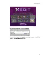
Page 74: ... workspace as a sandbox into which you will always first import the database you wish to work on during the current session and from which you will export the database at the end of the session To open XEdit 1 Double click the XEdit icon on your desktop A startup screen appears followed by the Database Locationwindow In XAdmin the virtual slot card concept is represented as follows Cards in virtua...

Page 75: ...XEdit Software 67 2 When prompted to specify the database location click Browse 3 Fromthewindowthatopens locateanappropriatedirectoryforyourworkspace andthenclickOpen to close the Select the database locationwindow ...

Page 76: ...x to avoid being prompted every time you open XEdit 4 Click OK to close the Database Location window The XEdit main window appears This may take a few seconds When first opening XEdit in offline mode the database contains the default configuration for a Kaleido X 7RU system including a fully populated frame all cards present and a set of predefined logical sources ...

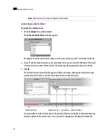
Page 77: ...by clicking theirX button 2 On the View menu point to Panes and tabs and then click Restore default window settings To close XEdit On the File menu click Exit Alternatively click the button in the upper right corner of the main application window Using XEdit Online When using XEdit inonline mode any changes made are applied and stored directly on the multi viewer WhenusingXEditinofflinemode allcha...

Page 78: ... to connect to from the list Otherwise type the appropriate IP address in the box 3 Click OK The selected system s hierarchical list appears in XEdit s main pane showing the multi viewer type system name and IP address and the status bar shows the connection status ItisalsopossibletoverifywhichversionoftheKaleido XSoftwareisinstalledonthismulti viewer by moving to pointer to the system name in the...

Page 79: ...database functions such asExport Import and Retrieve backup are not available Any changes made by the user are not kept locally on the user s PC but applied directly on the multi viewer To retrieve the data set from the multi viewer eitherdisconnectfromthemulti viewer andthenuse theImportfunction orusethe Create backupfunction to save a copy of the database A database can be retrieved from a backu...

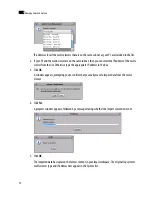
Page 80: ...t Otherwise type the appropriate IP address in the box 3 Click OK A window appears prompting you to confirm that you really want to import data from the multi viewer 4 Click Yes A progress window appears followed by a message stating whether the import succeeded or not 5 Click OK The imported data has replaced the former content in your local workspace The originating system s multi viewer type an...

Page 81: ...sh to transfer the database IP addresses for all the multi viewers that are on the same subnet as your PC are included in the list 2 IfyourPCandthemulti viewerareonthesamesubnet thenyoucanselecttheIPaddressofthemulti viewer from the list Otherwise type the appropriate IP address in the box 3 Click OK A window appears prompting you to confirm that you really want to export data to the multi viewer ...

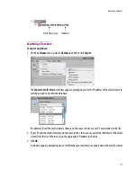
Page 82: ...Creating a Backup UsetheCreatebackupandRetrievebackupfunctionstomanagecopiesofyoursystemdatabase Thisis equivalent to the usual Save as and Open functions and is useful not only for security purposes but also on sites where more than one system must be maintained Backing Up the Current Database To back up the current system database 1 On the Configure menu point to Database then to Create backup a...

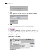
Page 83: ...scales from the current system 1 On the Configure menu point to Database then to Create backup and click Audio scales The Create Backup window appears 2 In Create Backup select the location where you wish to save a backup copy of the audio scales from the current database and then click Save The audio scales are saved as an XEdit collection file with a xcol extension Retrieving a Backup Retrieving...

Page 84: ...tention 3 Click Yes The former content of the local workspace is entirely replaced with data from the backup Retrieving Resolutions or Audio Scales from a Backup To retrieve resolutions or audio scales from a backup 1 On the Configure menu point to Database and then click Retrieve backup The Select Backup window appears 2 In Select Backup navigate to the appropriate backup file an XEdit collection...

Page 85: ... a Kaleido X 4RU or an expansion system then you need to replace the default multi viewer type To create a system with a single multi viewer 1 Launch XEdit 2 In the main window click the System tab and then click Description Calibrations on the second level tab bar ThemainpanedisplaystheSystemhierarchicallist andtheToolspanedisplaystheequipmentlibrary when the root of the System list is selected N...

Page 86: ...ight clickthelistroot andthenclicktheappropriatemulti viewertypeontheshortcut menu A message may appear prompting you to confirm your intention 4 Click Yes to have the system populated with factory defaults for the selected multi viewer type See Restoring Factory Defaults on page 87 for details Note If you deleted the initial multi viewer entry from the System list then the menu shows Insert optio...

Page 87: ...led Clickthemulti viewerintheSystemlist andthen inthePropertiestab specifythelogicalrouter and level you wish to control by selecting the appropriate values in the Router and Router level lists under TCP IP Router control 7 On the File menu click Save Alternatively click the Save button on the toolbar Changes to the system are saved Creating a Cluster Clusterscanonlybecreatedandconfiguredinonlinem...

Page 88: ...t have a unique name IfyouchangethesystemnameorIPaddressofaclustermemberwhileanotherclustermember isofflineorotherwiseunavailable thecluster sintegritywillbebroken Ifyouattempttomake such a change XEdit will alert you of the situation prompting you to cancel the operation and try again later when all cluster members are available If you choose to force the change then you will need to repair the c...

Page 89: ...entation on page 85 for detailed instructions on adding cards Refer to Routers Kaleido X on page 265 and Tally Interface Devices on page 311 for instructions on adding other routing and control devices 6 Once you have completed the current system s specific configuration save it and then connect to the next cluster member you need to configure by expanding the appropriate node and double clicking ...

Page 90: ...ilablesystemisindicatedbyadimmediconandcannot beexpanded Itcantakeupto15secondsbeforeamulti viewer sstatusiconisupdatedintheSystemlist Notes Eachroommusthaveauniquenameacrosstheclustersystem XEditwillnotletyouuseaname if there is already a room with this name associated with one of the multi viewers within the cluster All multi viewers associated with the cluster system must be available If one of...

Page 91: ...r the cluster configuration 1 InXEdit connecttoSystemB themulti viewerthatwasunavailablewhenthechangewasmade once it is available again Note Each layout must have a unique name across the cluster system XEdit will not let you export a layout to a cluster system if there is already a layout with this name associated with one of the multi viewerswithinthecluster Asaworkaround youcouldmakeacopyofoneo...

Page 92: ... 3911 control panel in iControl then repeat the previous steps for each If only the IP address was changed then no further action is required Otherwise if the system name was changed then proceed as follows 4 Connect to SystemA 5 Change something in every room e g move a display and then bring it back to its initial position to enable the Save button 6 Save the room This will replicate the proper ...

Page 93: ...e System root and the multi viewer The card slots appear in the hierarchical list If you already loaded the factory defaults for the multi viewer type then some slots are already populated with a card Note This topic applies to the Kaleido X 4RU Kaleido X 7RU and expansion systems only The Kaleido X16 and KMV 3901 3911 multi viewer models have virtual cardslots that represent a set of hardware fea...

Page 94: ... in the System list and then click Remove on the shortcut menu Alternatively click the populated card slot and then press Delete on your keyboard The slot is now empty and the card type does not appear any more Foreachemptyslotthatshouldbepopulatedwithacard right clicktheslotintheSystemlist and then click Insert card type on the shortcut menu Alternatively drag the card from the equipment library ...

Page 95: ...ds and logical sources as well as one predefined RCP2 user Admin However the default XEdit database does not include rooms or layouts If you wish to use default rooms and layouts as a starting point for building your system you can either import the default database from the multi viewer or use the Retrieve backup function to load the default database from the DVD shipped with the system In some s...

Page 96: ...store the XEdit factory defaults for a multi viewer 1 In the equipment library select the appropriate multi viewer type Kaleido Modular KMV 3901 3911 Kaleido X16 S Kaleido X16 D Kaleido X 4RU Kaleido X 7RU or Kaleido X 7RU 2 with expansion and drag it onto the root of the System hierarchical list Alternatively right click the list root and then click the system of choice on the shortcut menu A mes...

Page 97: ...s From a Specific Multi Viewer To restore factory defaults from a multi viewer 1 On the Configure menu point to Database and then click Import A window appears prompting you for the IP address of the multi viewer whose factory default database you wish to import IP addresses for all the multi viewers that are on the same subnet as your PC are included in the list 2 IfyourPCandthemulti viewerareont...

Page 98: ...ult database for your multi viewer type for instance FR7_factory_default_DB zip if you have a Kaleido X 7RU select it and then click Open A message appears prompting you to confirm your intention 3 Click Yes Managing Multiple Databases Efficiently To avoid mistakes in managing databases especially when multiple multi viewers are involved it is recommended to follow the rules below Note See Retriev...

Page 99: ...eisonedatabasepermulti viewer Anexpansion system comprising two Kaleido X 7RU frames is also managed through a single database A cluster system includes one database for each multi viewer in the cluster When you have completed your changes create a backup of the current database and store it in a secure location on your PC In the case of a cluster or cascade system make a separate backup from each...

Page 100: ...mpletedyourchanges exportthedatabasefromtheworkspace backtothe multi viewer Applying a Backup Database to the Multi Viewer To retrieve a backup database you must use XEdit in offline mode A backup database must first be restored to your local workspace before it can be exported back to the appropriate multi viewer To retrieve a backup database 1 On the Configure menu point to Database and then cli...

Page 101: ...nline mode calibration changes become immediately effective When using XEdit in offline mode calibration changes are applied to the system representation in your local workspace Multi Viewer Output Calibrations Brightness Thegreen red andblue brightness parametersdeterminetheblack level of theRGBoutputsignalsshownonthecorrespondingdisplay See Calibrating the Brightness and Contrast on page 96 Cont...

Page 102: ... Multi Viewer Input Calibrations Detail enhancer The purpose of the detail enhancer parameter is to recover sharpness that mayhavebeenlostinthede interlacingandscalingprocess See Calibrating Detail Enhancement and Dynamic Range on page 111 Dynamic range The dynamic range parameter determines the color model to be applied either full range RGB 0 255 or video RGB 16 235 Full range RGB is also called...

Page 103: ...el to be applied totheselecteddigital embedded orfromABT audiosignal dBFSstandsfor decibelsfullscale Zero dBFS corresponds to the maximum possible level By defaultthereferencelevelforaitissetto 20 dBFS onarangeof 24 dBFSto 8 dBFS The extraction of digital audio requires the KXS HD EMB or KXS SD EMB option see Enabling Options on page 371 Refer to Calibrating Zero VU Reference Level for an Embedded...

Page 104: ... determines whether the router module will perform clean crosspoint changes on the odd field 1 on the even field 2 field or on any field See Calibrating Switch Field Selection on page 115 SDI output reclocking TheSDIoutputreclockingparameterdeterminewhetherdigitalvideosignals will have their timing restored at the selected output to eliminate jitter Reclockingistypicallyusedininstallationswithlarg...

Page 105: ...tem appears 2 In the list expand the multi viewer whose output heads you wish to calibrate 3 Expand the appropriate output module The expanded module will show theoutput heads Depending on the multi viewer model other items may also appear 4 Select the head you wish to calibrate 5 Click the Properties tab The brightness and contrast adjustment controls appear Expand the headings to show the contro...

Page 106: ...ne and adjusting the sliders to the same value for the selected parameter Note Moving the Green master slider will move the Red and the Blue sliders by the same amount The values must be between 0 and 100 A good approach is to set all values the same using the Red and Blue sliders then to adjust for the best overallpresentationusingtheGreen master slider andfinallytofine tunethecolorbalanceusingth...

Page 107: ...ationcontrolprovides this function The color saturation calibration does not affect the graphical elements within the monitor wall display To calibrate the color saturation 1 In the main window click the System tab and then click Description Calibrations on the second level tab bar A hierarchical list representing the current system appears 2 In the list expand the multi viewer whose output heads ...

Page 108: ...mentsonthemonitorwalldisplaydrivenbytheselectedhead Alternatively typeavalue between 0 and 100 directly in the Color saturation box 7 If appropriate you may copy the settings from this head to everyoutputhead in the system To apply the color saturation settings globally throughout your system click Apply to all Thishasthesameeffectasselectingeveryoutputheadonebyone andadjustingtheColorsaturation s...

Page 109: ...ow click the System tab and then click Description Calibrations on the second level tab bar A hierarchical list representing the current system appears 2 In the list expand the multi viewer whose output heads you wish to calibrate 3 Expand the appropriate output module The expanded module will show theoutput heads Depending on the multi viewer model other items may also appear Note The KMV 3901 39...

Page 110: ...ng output is simultaneously available on one AES and two analog connections For each head output parameters can be adjusted to optimize the relative timing of the audio and video signals on the monitor wall display TheAudio monitoring delay calibration control provides this function To calibrate the audio monitoring delay for a head 1 In the main window click the System tab and then click Descript...

Page 111: ...panded module will show theoutput heads Depending on the multi viewer model other items may also appear 4 Select the head you wish to calibrate 5 Click the Properties tab Theaudiomonitoringdelayadjustmentcontrolappears ExpandtheCalibrationheadingtoshowthe control if it is not visible ...

Page 112: ...stem To apply the audio monitoring delay calibration globally throughout your system click Apply to all This has the same effect as selecting every output head one by one and adjusting the audio monitoring delay settings to the same values Calibrating the Audio Monitoring Color To calibrate the audio monitoring color 1 In the main window click the System tab and then click Description Calibrations...

Page 113: ... 4 Select the head you wish to calibrate 5 InthePropertiestab clickAudioMonitoringColor andthenclickthebuttonthatappearsattheend of the line 6 In Pick a Color click the tab that corresponds to the color space you wish to use and then choose the color that will be associated with the selected output head 7 Click OK to close the color picker window Click to open the color picker window ...

Page 114: ... current system appears 2 In the list expand the multi viewer whose inputs you wish to calibrate 3 Expand the appropriate input then one of its embedded audio elements and select Zero VU ZeroVUaudioselection 4 In the Properties pane set the reference level to the appropriate value in dBFS using the Zero VU slider under Calibration Alternatively type the value directly in the Zero VU box ZeroVUrefe...

Page 115: ...ties tab 5 Set the reference levels to the appropriate values in dBFS and in dBu using the Zero VU sliders under Calibration Alternatively type the values directly in theZero VU boxes ZeroVUreferencelevelselection 6 Click Apply to all to apply the chosen Zero VU reference values throughout the system Calibrating Dolby VANC Loudness Measurement To calibrate an audio source 1 In the main window clic...

Page 116: ...ence dialnorm value in the box or set it using the slider The default valueis 27dB onascale of 60dbto 0dB This value can then be compared against the measured loudness and against the encoded dialnorm found in the Dolby VANC data Loudness Channel Selection Select the check boxes corresponding to the audio channels that should contribute to the loudness measurement Loudness Standard Selectthestanda...

Page 117: ... value The measured levels and the encoded dialnorm can be compared against each other and against your organization s expected dialnorm and alarms triggered in case of too much deviation Max upper deviation The Max upper deviation parameter determines the tolerated excursion range above the reference value The measured levels and the encoded dialnorm can be compared against each other and against...

Page 118: ...edded audio 8 to be decoded in Dolby E Calibrating Automatic Aspect Ratio Decoding Aspect ratio information can be encoded following different standards The following table shows the different standards and their availability according to the signal type Standard Signal type HD SD 525 SD 625 WSS Yes AFD VI Yes Yes AFD 2016 Yes Yes Yes ...

Page 119: ...ct the appropriate value from theSD AFD Source list ThedefaultvalueisAutowhichmeansthatthemulti viewerwillautomaticallydetectwhatispresent in the signal and use it to report AFD If more than one AFD type is present in the signal and the SD AFDSourceissettoAuto thenAFDtypeisselectedinthisorder 1 AFD 2016first 2 AFD VI or 3 WSS 7 Click Apply to all to apply the associated setting to all video inputs...

Page 120: ...ensettheappropriatevalue between0and 15 in the Properties tab 5 Click Dynamic Range and then set the appropriate value either Full Range or Video Range in the Properties tab Calibrating Subtitling Closed Captioning To configure Teletext Subtitling page selection 1 In the main window click the System tab and then click Description Calibrations on the second level tab bar A hierarchical list represe...

Page 121: ... and then click Description Calibrations on the second level tab bar A hierarchical list representing the current system appears 2 In the list expand the multi viewer whose inputs you wish to calibrate 3 ExpandtheappropriateVideoelement selectthemetadataelementwhoseholdingtimeyouwishto configure and then set the relevant values under Calibration in the Properties tab Note On the monitor wall only ...

Page 122: ...60 seconds after which subtitles are cleared XDS filtering Set the holding time between 5 and 360 seconds for each XDS metadata element APS ASB CGMS A channel number elapsed time network name program description ID name length and type stationID TSIDname timeofday timezone V chiprating ...

Page 123: ...odule 1 In the main window click the System tab and then click Description Calibrations on the second level tab bar A hierarchical list representing the current system appears 2 In the list expand the multi viewer you wish to calibrate 3 Expand the appropriate router module and then click Switch Field Selection DTVCC holding time Set the delay between 15 and 360 seconds after which closed captions...

Page 124: ...nal Reclocking To calibrate reclocking of a router module s output signal 1 In the main window click the System tab and then click Description Calibrations on the second level tab bar A hierarchical list representing the current system appears 2 In the list expand the multi viewer you wish to calibrate 3 Expand the appropriate router output and then click SDI Output Reclocking ...

Page 125: ...t purposes To configure a GPI line s direction as an output 1 In the main window click the System tab and then click Description Calibrations on the second level tab bar A hierarchical list representing the current system appears 2 In the list expand the multi viewer you wish to calibrate 3 Expand the GPI GENLOCK module and then click the appropriate GPI line element 4 In the Properties tab click ...

Page 126: ...118 Calibrating the Kaleido X 5 6 TosetthisGPIoutputline sON OFFstatesetmanuallyfortestpurposes clicktheGPIOutbox andthen select either ON or OFF from the list ...

Page 127: ...ows the filtering of false alarms To filter false alarms several parameters can be calibrated including the duration of the potential alarm event how often this event occurs during a specific period called the detectionwindow and the length of this detection window An alarm occurrence not the alarm itself is detected when a probe is in a continuous error state for the number of seconds specified i...

Page 128: ...pported for Gateway alarms only Error or Critical Error detected Disabled Covers multiple conditions No alarm assigned to the status indicator Alarm exists but is disabled at the source by the user The Kaleido X has the ability to deactivate some alarms on the hardware itself Alarm exists but was not reported yet The software is waiting for the hardware or driver to update the alarm Alarm that has...

Page 129: ...or include the item GlobalAlarm along with all the individual alarm levels You can select this global alarm not only as an alarm status but also as a text label level When an individualalarmisinError itsfriendlynamewillcontributetotheglobalalarmtextvalue Whentheglobal alarmlevelisassignedtoanalarmmonitor thetextvaluesforallcontributingalarmscurrentlyinErrorwill be visible Virtual Alarm A virtual a...

Page 130: ...ormation The following table contains a list of supported video formats and the type of captioning teletext or subtitling data that is decoded by default for each video format when a video monitor s text mode is set to Auto sense DTVCC 708 CC 608 teletext OP 47 or WST or none Note TheEIA 708standardsupportslegacyEIA 608data InthecaseofanHD SDIsourcecarryingboth 708 captions and 608 legacy caption ...

Page 131: ...orm for program 1 for each source If multichannel audio up to 16 channels is transported as regular AES channels up to 8 in the SDI embedded audio metadata is extracted from VANC packets 1080i 50 Hz 25 Hz PSF Teletext NTSC N CC 608 1080p 25 Hz Teletext NTSC J CC 608 1080p 25 Hz EM Teletext SECAM Teletext 1080 25PSF EM Teletext Component Y Only 525 None 1080p 23 98 Hz 24 Hz DTVCC 708 Component Y On...

Page 132: ...navailable is displayed if the source is not being decoded or is not Dolby E Logical Source Assignment Logical source assignment is performed by dragging an AES pair onto a logical source s audio level Term Definition Dolby E Stream A coded compressed 8 channel digital stream that fits inside an AES channel L R Dolby Metadata Metadata of Dolby E type such as dialnorm and programconfig Dolby E Extr...

Page 133: ...e logical source Detailed Directions Configuring Video Audio Alarm Threshold To configure the threshold for a video or audio alarm 1 Connect to the multi viewer you wish to configure if you wish to apply the changes in real time see Connecting to a Multi Viewer on page 70 2 In the main window click the System tab and then click Description Calibrations on the second level tab bar 3 Navigate to the...

Page 134: ...which Luma Too High will be reported Freeze sensitivity Freezedetectionisdonebycomparingsuccessiveframes Noiseinthesignal could disrupt this process so filtering is added to remove it Adjust the sensitivity according to the signal being monitored on a range of 0 for a noisysignal to16 foracleansignal Bydefaultthesensitivityissetat8 and the alarm will be triggered after 3 occurrences of a least 5 s...

Page 135: ... right Select the level in dBFS dB or dBu depending on the signal source below which the audio signal will be considered silenced Out of phase Select the sensitivity level below which the audio signal will be considered out of phase The sensitivity is a value between 1 and 1 where 1 means completely out of phase and 1 means perfectly in phase Mono An audio source is considered to be mono if the le...

Page 136: ... Display alarm status information from Densité cards on the monitor wall Display alarms detected within a Kaleido X system on an iControl Web page Display alarm status information in XEdit online mode Create virtual alarms that combine a number of alarm statuses not only within a single system but also from different devices within multiple Kaleido X and iControl systems Note If this step is omitt...

Page 137: ...whose alarm providers you wish to define 3 In the Properties tab click the Alarm providers list box 4 Click the button that appeared at the end of the box to open the External Alarm Providers Configuration window 5 Addorremovealarmprovidersasneeded andthenclickOKtoconfirmandapplythechanges orclick Cancel to close the window without saving your changes to the external alarm providers list To add an...

Page 138: ...tem tab and then click Description Calibrations on the second level tab bar A hierarchical list representing the current system appears 2 Expand the multi viewer whose alarms you wish to log navigate to the appropriate alarm and then click the alarm to select it Note By default native alarms are not logged but virtual alarms and global alarms are always logged In addition when a virtual alarm stat...

Page 139: ...enabled for all desired alarms 6 On the File menu click Save Alternatively click the Save button on the toolbar Publishing Alarms to SNMP Devices The Kaleido X and Kaleido X16 multi viewers support the use of Simple Network Management Protocol SNMP traps to notify an external SNMP manager of significant events These significant events are flagged within the Kaleido X system as alarms Two actions a...

Page 140: ...unitybox whichcontains public bydefault andthentypea new name for the group of target SNMP managers 4 Click the Trap targets box 5 Click the button that appeared at the end of the box to open the SNMP Configuration window The trap targets list showsall trap targets currently identified for the selected multi viewer SNMP Managers that are trap targets for this multi viewer are identified by their h...

Page 141: ... wish to remove in the list It becomes highlighted and its host address and port number appear in the data boxes 2 Click Delete The trap target is removed from the list Enabling SNMP Traps The multi viewer analyses the signals that pass through it and can detect and flag problems by raising alarms Each alarm can be individually configured Most alarm definitions specify detection thresholds and det...

Page 142: ...elect it 3 InthePropertiestab selecttheTrapenabledcheckboxtohavethemulti viewerissueanSNMPtrap each time this alarm is triggered 4 Click Apply to all to apply this setting to allotheralarmswiththesamename throughout the system Intheexample clickingApplytoallwillenableVideoLossSNMPtrapsforeveryinputinyoursystem 5 Repeat the procedure until all desired SNMP traps have been enabled 6 On the File menu...

Page 143: ...ntation refersto a group of physical audio video or metadata sources and text attributes A logical source can be used as a whole and assigned to a virtual monitor Level Within a logical source attributes are organized bylevels belonging to one five categories Video Audio Text Alarm and Time code For example the video level categorymaycomprisemultiplelevels eachrepresentingaspecificphysicalpartof a...

Page 144: ...l sources and a preconfigured KXRouter logical router Adding a Logical Source To add a logical source 1 Click the Channels Sources tab in the main window The sources table appears Incremental copy Once a logical source channel is configured it is possible to use incremental copy to automatically propagate appropriate physical assignments to other adjacent logical sources For instance if the curren...

Page 145: ... one level under each level category A symbol indicates the physical source for each assignment for example A16 indicatesinputsignal16oninputcardA Inthecaseofanexpansionsystem thesymbolisprefixed with a frame identifier either FRA or FRB On the Kaleido X16 only the input numbers 01 to 16 appear On a KVM 3901 3911 the input number 1 to 8 appear Note You can change the logical source name and path F...

Page 146: ... this logical source Making Further Assignments by Incremental Copy Once done with a first logical source if the next logical source is to be similar to the first one it is possible to use incremental copy to automatically create it Alternatively if only one or a few specific levels are to be similarly configured it is possible to use incremental copy on the corresponding level column only To use ...

Page 147: ...are now populated with incremented physical assignments Adding Levels To add a level 1 Click the Channels Sources tab in the main window Note It is possible to drag the incremental copy zone up or down The physical assignments will be decremented or incremented accordingly Note To be able to monitor a 3D stereoscopic signal you must first add a second video level to your logicalsources soyouhaveal...

Page 148: ...ave button on the toolbar The sources table is saved Sorting the Sources Table To sort the sources table Right click the heading of the column you wish to sort by i e either Source ID or any of the level headings and then click Sort on the shortcut menu The sources table is sorted based on the elements in the selected level Note To change the level name click theProperties tab and then type the ne...

Page 149: ...dth is adjusted to fit the content To resize all columns to the width of their content In the category or level heading row point any column boundary until the pointer becomes a resize pointer and then triple click All columns are resized to fit their content Configuring Alarm Levels To assign an alarm to a logical source s alarm level 1 Click the Channels Sources tab in the main window 2 In the s...

Page 150: ...ces tab in the main window 2 Add a logical source to the table see Adding a Logical Source on page 136 3 In the new logical source row click the cell that corresponds to the first video level 4 Expand the filtered System list in the Tools pane locate the router output you wish to monitor and drag it onto the selected cell in the sources table 5 On the File menu click Save Alternatively click the S...

Page 151: ... source is available you can also assign it to other composite or video monitors directly on the monitor wall and their video window will dynamically follow the video signal sent to that router output Note ThecurrentversionoftheKaleido XSoftwaredoesnotsupportmonitoringoftheassociatedaudio signal ...

Page 152: ...144 Creating Logical Sources 7 ...

Page 153: ...sameroom Thegroupingofdisplaycreatesalargevirtualmonitor wall that operators see as a single large display The room definition specifies display resolutionsand sizes aswell aszones that are used to displayfullscreen layouts Display versus monitor Within the XEdit workflow a display refers to the representation of a physical display monitor such as a CRT within a room whereas a monitor represents a...

Page 154: ...e Save button on the toolbar The Save Room window appears Full screen zone A full screen zone is a sub section of a room It can be any size and it can be positionedonanyofthedisplaysintheroom Afullscreenzonecanbeassociated with one or more full screen layouts assigned to specific users Display library A display library contains a collection of predefined displays that can be conveniently reused to...

Page 155: ...cters Inaclustersystem eachroommusthaveauniquenameacrossthewholesystem XEditwillnot let you use a name if there is already a room with this name associated with one of the multi viewers within the cluster In a cluster system if one of the member multi viewers becomes unavailable while you were configuring a room then XEdit will not let you save the room If you wish to save the room anyway first re...

Page 156: ...vely click the Close button on the toolbar Adding Displays To add a display to a room 1 Select a display from the display library and drag it onto the room area Alternatively clicktheDisplaybutton onthetoolbar andthenclicktheroomareatoaddacustom display Note In the case ofa cluster system it is possible toview aroom configuration in offline mode but any changes must be made in online mode ...

Page 157: ...ead navigate to the appropriate output card and then click the output head you wish to assign to this display Note All currently open display libraries appear on the Tools pane Custom display libraries are stored separately from the XEdit workspace See Managing Display Libraries on page 166 for details Filtered System list Display library Room area Selected display Properties of the selected displ...

Page 158: ... When different displays are assignedthesameoutputhead ifthedisplaysarepartofthesameroom thenXEditwillissueanerror message and prevent you from saving the room until the head assignment is corrected However to facilitate room management XEdit will let you assign the same head to displays that are located in different rooms but such conflicting assignments will be marked in red in the filtered Syst...

Page 159: ...e systems the dashboard may show the wrong room name from one of the earlier standalone configurations To prevent this from happening open the old room configuration and look for red Head elements in the filtered System list that appears at the bottom of the Tools pane Clear the unwantedheadassignments eitherbyremovingthecorrespondingdisplaysfromtheroomlayout orby completely deleting the old room ...

Page 160: ... a specific display in a room In addition to monitor wall displays your system can include other monitors connected to the multi viewer sHD SDI outputs one for each output head available with theSDImonitoringoutput option The HD SDI outputformaton agivenhead depends on the resolution configuredforthecorrespondingmulti viewer output and in the case of a 1080 line resolution on the selected scan for...

Page 161: ...monitor resolutioncheck box Note The monitor EDID Auto detect feature is enabled by default in order to facilitate the initial setup ofaKaleido Xsystem Toavoidproblems Mirandarecommendsthatyoudisabletheauto detectfeature once the initial setup is completed If you later wish to replace one of the displays re enable the auto detect feature beforehand remember to disable it once the new display is up...

Page 162: ...Save button on the toolbar Configuring Custom Resolutions from the Tools Menu To create a custom display resolution from the Tools menu 1 On the Tools menu click Edit resolutions The Edit Resolution Settings window appears Select to enable automatic detection of EDID information ...

Page 163: ...lankstart syncstart syncendandblankend setthe refreshrateandothertimingparameterssothat theymatchthoseofthephysicaldisplayyouneedto configure Note When you modify one of the default resolutions you can only save your changes as a new resolution Ontheotherhand customresolutionscanbetweakedandsavedrepeatedlyuntilthedesired configurationisachieved However makesurethattheactivewidthandactiveheightvalu...

Page 164: ...d to copy to the Modeline section of the Edit Resolution Settings window Note In XAdmin s Status and Options page these parameters are listed under the corresponding output card information according to the blank sync start end modeline system and with the sync polarityexpressedasanumberbetween0and3 Referto ViewingaMulti Viewer sStatusInformation on page 386 for details ...

Page 165: ... if you are modifying an existing custom resolution you can click the Save button Configuring a Custom Resolution from a Specific Display in a Room To configure a custom resolution from a specific display in a room 1 Click the display whose properties you wish to configure 2 ClicktheResolutionboxinthePropertiespane andthenclickthebuttonthatappearedontheright of the resolution presets Type a name ...

Page 166: ...rch or the Modeline section depending on whether you prefer to specify front porch backporch sync andactivevalues orblankstart syncstart syncendandblankend setthe refreshrateandothertimingparameterssothat theymatchthoseofthephysicaldisplayyouneedto configure Edit Resolution Settings button ...

Page 167: ...heimagebelowshowstherelevantdatayouneedtocopytotheEditResolution Settings window Note In XAdmin s Status and Options page these parameters are listed under the corresponding output card information according to the blank sync start end modeline system and with the sync polarityexpressedasanumberbetween0and3 Referto ViewingaMulti Viewer sStatusInformation on page 386 for details ...

Page 168: ... Alternatively if you are modifying an existing custom resolution you can click the Save button 5 On the File menu click Save Alternatively click the Save button on the toolbar Changing Room Display Resolutions To change the resolution for a display in a room 1 Click the display you wish to configure 2 Click the Resolution box in the Properties pane The resolution presets appears ...

Page 169: ...lingEDIDAuto DetectioninXEdit onpage153 Thefollowing multi vieweroutputresolutionsaresupported 1920 1080 foranHD SDIoutputinthe1080ior1080p format and 1280 720 for an HD SDI output in the 720p format Any other DVI RGBHV resolution will result in the HD SDI output being disabled To configure the scan format for a 1080 line signal at the SDI monitoring output 1 IntheRoomarea clickthedisplayassociate...

Page 170: ...o of a display in a room 1 Click the display whose properties you wish to configure 2 Click the Aspect ratio box in the Properties pane The aspect ratio presets appear Notes It is important to properly set the aspectratio of a display since this willaffectthe proportions ofeverycomponentyouwillusetocreatelayoutsforthisroom Forinstance iftheaspectratio of a display does not match the aspect ratio o...

Page 171: ...olbar Changing a Display s Diagonal Size To change the diagonal size of a display in a room 1 Click the display whose properties you wish to configure 2 Click the Diagonal size box in the Properties pane Diagonalsize 3 Select the appropriate unit of measurement from the list that appears inside the Diagonal size box and type the size 4 On the File menu click Save Alternatively click the Save butto...

Page 172: ...urementfromthelistthatappearsinsidetheHeightboxandtype the height 4 On the File menu click Save Alternatively click the Save button on the toolbar Changing a Display s Width To change the width of a display in a room 1 Click the display whose properties you wish to configure 2 Click the Width box in the Properties pane Width property 3 Select the appropriate unit of measurement from the list that ...

Page 173: ...anging a Display s Position To change position of a display in a room 1 Click the display whose properties you wish to configure 2 Click the Position box in the Properties pane then click the button that appears inside the box The Specify Position window appears Notes The current version of the KMV 3901 3911 multi viewer does not support display rotation TheDisplayRotationoptionmustbeenabledonthec...

Page 174: ...n which you do not want the dashboard to appear and then clear the Allow dashboard display check box in the Properties pane Managing Display Libraries Thedefaultdisplaylibraryincludesconfigurationsforthemostpopulardisplaymodels Youcanalsocreate your own display configurations and add them to custom display libraries All open display libraries appear on the Tools pane The default display library is...

Page 175: ... display library area and then click New display library on the shortcut menu Displaylibrary shortcutmenu The new display library appears below the default display library area in the Tools pane 4 Right click anywhere in the display library area and then click Save Display Library on the shortcut menu The Save Display Library window appears 5 Type a name for the new custom display library and then...

Page 176: ...arywhileholdingtheCtrlkey Removing Displays From Custom Libraries To remove a display from a custom library Click the display you wish to remove and then press Delete Alternatively right click its icon and then click Delete entry on the shortcut menu Note Itisnotpossibletofurthercustomizeadisplayonceitisinsidealibrary Shouldyouneedtodoso drag the display to the room area apply the required changes...

Page 177: ...ibrary on the shortcut menu Alternatively click Close display library on the File menu Opening Display Libraries To open a custom display library IntheToolspane right clickanywhereinthedisplaylibraryarea andthenclickOpendisplaylibrary on the shortcut menu Alternatively clickOpen display library on the File menu Note It is possible to have multiple custom libraries open at the same time ...

Page 178: ...170 Setting Up Rooms 8 ...

Page 179: ... and sizes There are two types of layouts room layouts and full screen layouts Monitor A monitor also called widget is a graphical element that is part of a layout XEdit supports several types of primitive layout elements e g clocks video monitors audio monitors UMDs time code monitors etc as well as composite monitors Video monitor A videomonitor is a layout element used to define an area for dis...

Page 180: ...in two ways Video monitor slaved to input A video monitor can be slaved to the input format such that the video monitor will change its aspect ratio according to the input signal type e g SD HD DVI VideorasterfollowsAFD WSS Avideomonitorcanbeconfiguredsothat WSS AFDVI orAFD 2016metadataisusedtocrop and oraddblackbars to the video signal giving the video raster the correct aspect ratio This metadat...

Page 181: ...ndconfiguredinXEdit Timermonitorscanbeconfigured directly on the monitor wall See Configuring Timers on page 207 Alarm monitor Alarmmonitorshelpyouseethestatusofglobalandvirtualalarms buttheir use is not limited to this type of alarms When any alarm level is assigned to an alarm monitor the status of this alarm is shown When using the global alarmatthetext labellevel thealarmmonitordisplaysthetext...

Page 182: ...to the appropriate layout and then click Open The selected layout appears in the Layouts tab Loading a Layout on the Monitor Wall To load a layout on the monitor wall directly from XEdit when working in online mode Click the LOAD button on the toolbar ...

Page 183: ...button on the toolbar Creating Room Layouts To create a room layout 1 Click the Layouts tab in the main window 2 On the File menu click New The CreateaNew Layout window appears Itlistsalltheexistingroomsandfullscreenzonesinyour system 3 Click the name of the room where this layout will be displayed An empty layout appears 4 Add at least one monitor to the layout ...

Page 184: ...reen layout 1 Click the Layouts tab in the main window 2 On the File menu click New The CreateaNew Layout window appears Itlistsalltheexistingroomsandfullscreenzonesinyour system Note In the case of a KMV 3901 3911 multi viewer layouts are subject to the following limitations up to eight video monitors over two displays overlapping is not supported up to four stereo audio level meters per video mo...

Page 185: ...gnateoneofthemwho willreceiveitssourceassignmentsfromthemonitorunderthemousepointeronthemonitorwall by selecting the Full screen layout monitor option in the Properties pane Maketheappropriateassignmentsfortheotherelementsinthelayout see AssigningLogicalSources or Monitor Wall Destinations to Monitors on page 182 5 On the File menu click Save Alternatively click the Save button on the toolbar The ...

Page 186: ...te In the case of a KMV 3901 3911 multi viewer layouts are subject to the following limitations up to eight video monitors over two displays overlapping is not supported up to four stereo audio level meters per video monitor one time code per video monitor only digital clocks are supported XDS metadata monitors are not supported Note All open widget libraries appear in theTools pane Seealso For de...

Page 187: ...zed and positioned for monitor spanning Notes Monitors can extend outside the edge of a display but not completely The use of a mouse is not completely supported with spanned video monitors In the case of a KMV 3901 3911 multi viewer which supports a maximum of eight video monitors over two displays a spanned video monitor counts as two i e if you have one spanned video monitor you can only add si...

Page 188: ...ly press Ctrl D A copy of the monitor is added to the layout 3 Move the new monitor to the appropriate position on the layout 4 Press Ctrl D again and repeat until the desired number of copies of the monitor are added to the layout Thenewcopiesareautomaticallypositionedatintervalsmatchingtherelativepositionsoftheoriginal monitor and its first duplicate Automatically Populating a Grid Type Layout U...

Page 189: ...corner of the current monitor and the bottom right corner of the current head and then click OK Thefirstmonitorisresizedandreplicateduntilthegridareaispopulatedwiththespecifiednumberof monitors Copying layouts To copy a layout 1 Open the layout you wish to duplicate 2 On the File menu click Copy layout to point to the appropriate room and then either select an existing layout from the list or clic...

Page 190: ...ich you can make assignments by dragging logical sources and monitor wall destinations onto monitors To assign a logical source to a monitor SelectalogicalsourcefromthefilteredChannels Sourceslist intheToolspane andthendragitonto the appropriate monitor To assign a monitor wall destination to a monitor SelectadestinationfromthefilteredMonitorwalldestinationslist intheToolspane andthendrag it onto ...

Page 191: ...in Select Image then click the Open button to open the Browse Image window Locate the image select it and then clickOpen The image is imported into the current database 5 In Select image select the image file from theImage selection list and then click OK Note The maximum size for each image is 256 KB and the maximum overall size for all images is 10 MB The image can be in PNG GIF or JPEG format I...

Page 192: ... a layout s background to be keyed out and replaced with content from the DVI input To use the DVI input as the background in a layout 1 Click the background of the layout 2 InthePropertiespane clicktheBackgroundcolorbox andthenclickthebuttonthatappearsinside the box to open the Pick a Color window Note The KMV 3901 3911 multi viewer does not support DVI keying Note Since the DVI input cannot be r...

Page 193: ...inputwill be displayed in thecorresponding areason the monitor wall If there is no signal at the associated DVI input or the multi viewer does not support DVI input as would be the case with a KMV 3901 3911 residual data may be visible in such areas Pass through colors RGB 254 0 254 254 0 255 254 1 254 254 1 255 255 0 254 255 0 255 255 1 254 255 1 255 Donotusethesecolorsforanymonitor scolorattribu...

Page 194: ...om in or the minus key to zoom out Press and hold the Ctrl key then rotate the mouse wheel to zoom in or out Type the zoom factor you wish to apply in the range of 2 to 1600 directly in the zoom box Press and hold the spacebar then click and drag to pan Use the scroll bars at the right side and bottom of the Layouts or Rooms tab In the case of a layout view click and drag the layout navigator s re...

Page 195: ...Change the aspect ratio property of the video monitor See Setting a Video Monitor s Aspect Ratio below The video monitor will keep its bounds and the video window will be resized to fill as much of the video monitor area as possible given the new aspect ratio Setting a Video Monitor s Aspect Ratio To set a video monitor s aspect ratio 1 Click the video monitor whose aspect ratio you wish to config...

Page 196: ...t ratio box The box becomes editable 3 Type the appropriate aspect ratio and then press Enter Thenewaspectratioisappliedtothevideowindow withinthevideomonitor anditisaddedtoboth the Current aspect ratio and Custom aspect ratio lists Note Double click the video if is part of a composite monitor Note The custom values are appended to the Custom aspect ratio list on an ongoing basis They can then be ...

Page 197: ...age can be in PNG GIF or JPEG format To add a free form safe area image to a video monitor 1 Open an existing layout or create a new one 2 Click an existing video monitor in the layout or create a new one 3 In the Properties pane select the Show markers check box under Safe area markers 4 Click the Custom safe zone image box Note Double click the video if is part of a composite monitor Note The ma...

Page 198: ...lect Image then click the Open button to open the Browse Image window locate the image select it and then click Open The image is imported into the current database 7 In Select image select the image file from theImage selection list and then click OK Note Images can be used on multiple layouts and only need to be imported to the database once Select image button ...

Page 199: ...vethe slider or type the desired transparency value directly in the box At 0 the portions of the image that correspond to the unsafe area are opaque at 100 the entire image is transparent Note When a custom safe zone image is selected the following attributes are not available Marker color Safe title offsets Safe zone aspect ratio and Unsafe zone color ...

Page 200: ...dvideosignal from the drop down menu beside Mode Changing the underscan overscan mode dynamically It is also possible to dynamically change the overscan underscan mode based on a feed assigned to a video monitor For example you can change logical sources in a video monitor using Gateway commands where a video source requires the monitor to be in overscan mode but a graphics source requires the mon...

Page 201: ...ins then click OK When the layout is loaded on the Kaleido X the updated overscan underscan properties become available Note Generally avoid exceeding 15 in any direction You can click Restore defaults to enter the defaultoverscanvalues left right topandbottom 5 Safetitleareaandaspectratiomarkersfollow thevideosignal e g ifthesafetitleiswithin5 oftop left rightandbottom thenwhenthevideoisin defaul...

Page 202: ...barsto thevideosignal givingthevideorasterthecorrect aspectratio ThismetadatacanbereportedasfriendlytextinsideaUMD Itspresencecanalsobemade available in alarms as well as via SNMP traps TheAutomaticAspectRatiofeaturecanalsobeconfiguredforeachvideoinput see CalibratingAutomatic Aspect Ratio Decoding on page 110 To slave a video monitor to the input signal aspect ratio 1 In the Layouts tab select th...

Page 203: ...the default value for thecurrent format i e Default HD AFD Value if the input is HD or DefaultSDAFD WSSValueistheinputisnotHD isused IftheDefaultisNone thentheinputfeed aspect ratio is used 3 Click the Save button To have a video raster to follow a video signal s AFD WSS metadata 1 Click to put a check mark in the box labeled Follow AFD WSS 2 Chooseavaluefromthedrop downmenubesideDefaultSDAFD WSSv...

Page 204: ...capable of displayinganalarmstatus e g videomonitors UMDs alarmmonitors canbeconfiguredwithalatching mechanism An alarm latch will keep the error state visible until someone acknowledges the associated alarm Video monitors can provide alarm status information through their borders color and blinking behavior and show the latched state as small indicators in each corner of the video window To set t...

Page 205: ...rner of the video window Blink mode Description Off The status indicator will never blink Follow Latch The status indicator s blinking will follow the latch status The indicator will blink until someone unlatches the alarm Critical The status indicator will blink when the current status is critical Critical or Major The status indicator will blink when the current status is critical or major Criti...

Page 206: ...2 Select the Text enabled check box 3 Select a value from the Text mode list 4 Select the appropriate option from the Text colors list Note Closed captioning subtitling text services can be enabled by purchasing the Extraction of CC Subtitling and XDS data option The CC 608 CC 708 XDS and Subtitling WST are all activated as a single option InthecaseoftheKaleido X 4RU andKaleido X 7RU models onekey...

Page 207: ...spane clicktheAudioscalebox underAppearance andthenselecttheappropriate audio scale from the list Notes The current version of the Kaleido X Software supports foreground colors for teletext WST OP 47 only Closed captions CC DTVCC will appear in white against a black background If you do not need teletext to be displayed in colors then you may find that selecting Black white will improve your syste...

Page 208: ...or less details where the audio is currently being monitored Clear the check box if you do not need this 4 UnderAssignments clicktheAudioformatbox andthenselecttheappropriateformatfromthelist 5 Make the appropriate assignments see Assigning Logical Sources or Monitor Wall Destinations to Monitors on page 182 and set the other attributes as needed Note See Configuring Audio Scales on page 201 for m...

Page 209: ...bally from the Tools menu or by clicking a specific audio monitor in a layout Configuring Audio Scales From the Tools Menu To configure an audio scale from the Tools menu 1 On the Tools menu click Edit audio scales The Edit Audio Scale window appears Note See Creating Actions on page 237 for more information ...

Page 210: ...ttons to set the top middle and bottom color The Choose Background Color window appears 4 Click the appropriate color square Swatches in the selected color appear under Preview Note When you modify one of the default audio scales you can only save yourchanges as a new audio scale On the other hand custom audio scales can be tweaked and saved repeatedly until the desired configuration is achieved ...

Page 211: ...n click the Save as button Alternatively if you are modifying an existing custom audio scale you can click theSave button Configuring an Audio Scale From a Specific Audio Monitor To configure an audio scale from a specific audio monitor 1 In the Layouts tab click the audio monitor you wish to configure 2 In the Properties pane click the Audio scale box under Appearance and then click the button th...

Page 212: ...desired 7 Enter the audio thresholds in Upper limit and Lower limit 8 Type a name for the new audio scale in the box at the bottom and then click the Save as button Removing Audio Scales From the System To remove a custom audio scale from the system 1 On the Tools menu click Edit audio scales The Edit Audio Scale window appears Note When you modify one of the default audio scales you can only save...

Page 213: ...t undertheLayoutstab selecttheaudiomonitorforwhichyouwishtoapplyaudiometadata settings then click the Properties tab 2 Choose the source associated with this audio monitor from theAudioformatlist Auto PCM Dolby E or Dolby VANC Note The default audio scales cannot be removed from the system Note To decode Dolby E audio metadata theDolbyE option KXS DolbyE is required See Enabling Options on page 37...

Page 214: ...t right and stereo IftheAudioformatissettoAuto DolbyEorDolbyVANC thentheavailablechoicesareleft right stereo surround leftsurround rightsurround LFE center leftbacksurround rightbacksurround left extra and rightextra 5 Choose a Dolby program 6 Specify a Friendly name Note Iftheactualaudiosourceassignedtothisaudiomonitorisnotofthesameformatconfiguredhere then the audio data will not be shown ...

Page 215: ...can be created modified deleted added to a layout assigned to logical sources rooms or individual RCP users and controlled from the Kaleido RCP2 Adding Timers to the System To define a timer 1 On the Tools menu click Edit timers 2 In Timer Editor click New 3 Type a name for your new timer in the Timer name box Note Inadditiontotimermonitors Gatewaycommandscanbeusedtointeractwithtimers Refertothe K...

Page 216: ...xt dayatthesamestart time Torestartit youmusteitherresetthetimermonitoronthemonitorwall orsetandspecifya new start time 5 Choose what happens when the timer reaches the end of its countdown period from the Timer end list Loop The timer restarts and repeats its cycle not available with the Remaining timer mode Stop The timer stops Overrun The timer counts through its specified end point and then co...

Page 217: ... eitheranembeddedtimecode signal from a video source an LTC input if available or the internal clock time default IMPORTANT Before setting a timer s start time in XEdit review the following Iftheselectedtimecodereferenceincludestimezoneinformation thenmakesurethat the PC or laptop that has XEdit is configured for the same time zone ...

Page 218: ...r to the multi viewer s internalclock then the multi viewer s system time will apply In the case of a Kaleido X or Kaleido X16 multi viewer model make sure the time zone settings are the same on the multi viewer and on the PC or laptop that has XEdit In the case of a KMV 3901 3911 when you save or export the timer to the multi viewer XEdit automatically converts the start time you specified to UTC...

Page 219: ...he Timers library to the layout The timer s attributes appear in the Properties pane 3 Replace the default name by typing a new name in the Name box 4 If you wish to assign a logical source drag the appropriate element from the Channels Sources list that appears in the Tools pane to the timer monitor The selected logical source s name appears in the Source box and the Timer source box shows the va...

Page 220: ...ce properties as needed Note The first time code level applies by default If your system s logical sources include more than one time code level select the one you wish to apply from the Time code level list Note Each timer monitor is assigned to exactly one timer Multiple timer monitors can be assigned to the same timer Start stop reset or mode changes applied to one monitor affect all other moni...

Page 221: ...save the action assignment and close the Action Editor window 12 Click Save to save the layout with the new timer monitor 13 Export the database to a Kaleido X and load the layout The interactive timer monitor appears on the Monitor Wall Note For more information on creating actions refer to Creating Actions on page 237 Note See UsingTimers onpage 53 AssigningaTimertoaRoom onpage255 and Assigninga...

Page 222: ... In the Layouts tab double click the UMD whose static text you with to set 2 Make sure the appropriate input language and method are set in your operating system 3 Type the desired static text To configure static UMD text from the sources table 1 IntheChannels Sourcestab clickthecellthatcorrespondstotheappropriatetextlevelofthelogical source that is assigned to the UMD whose static text you with t...

Page 223: ... mode boxes and then select the appropriate blinking behavior for your purposes Blink mode Description Off The status indicator will never blink Follow latch The status indicator s blinking will follow the latch status The indicator will blink until someone unlatches the alarm Critical The status indicator will blink when the current status is critical Critical and major The status indicator will ...

Page 224: ...sired value directly into the box Set the other appearance attributes as desired 3 In the Alarms Tallies section set the appropriate color and video transparency scheme for the text and background to achieve the desired alarm reporting behavior Note Onthe monitorwall an alarmmonitorpositionedover a video window has the following default behavior Ifthesourceassignedtothealarmmonitorisanactivealarm ...

Page 225: ...gnments see Assigning Logical Sources or Monitor Wall Destinations to Monitors on page 182 and select the desired alarm and text label levels if necessary 8 On the File menu click Save Alternatively click the Save button on the toolbar Blink mode Description Off The status indicator will never blink Follow latch The status indicator s blinking will follow the latch status The indicator will blink ...

Page 226: ...se to layer this monitor on top of the video window within a composite See Working with Composite Monitors on page 225 for instructions on how to add elements to a composite 2 In the Properties pane select the check boxes that correspond to the data elements you wish the monitor to display 3 You can also set appearance properties including the font and size of the text labels or choose not to disp...

Page 227: ...ithinanHDvideosignal To add a V chip monitor to a layout 1 Click the V chip monitor button on the toolbar click the layout and then move or resize the monitor as needed You may choose to layer this monitor on top of the video window within a composite See Working with Composite Monitors on page 225 for instructions on how to add elements to a composite 2 In the Properties pane set the transparency...

Page 228: ... predefined widget library includes a selection of analog and digital clocks Note Asitsnameimplies theV chipratingpreviewisonlyapreview anditsvalueisnotsavedwiththe layout Notes Unlike alarms the V chip rating associated with a video signal that is currently monitored on the monitor wall is not relayed to the XEdit user interface when working in online mode TheV chipmonitorusestheholdingtimeconfig...

Page 229: ...ical Sources or Monitor Wall Destinations to Monitors on page 182 and select the desired time code level if necessary Select the appropriate time zone for your purposes Notes The KMV 3901 3911 multi viewer does not support analog clocks InthecaseofaKMV 3901 3911 thesystemtimeisalwaysbasedonUTC However ifyouwish toseethetimefromdifferenttimezonesonthemonitorwall youcanconfiguredifferentclocks accor...

Page 230: ...not include time zone information then in the case of a Kaleido X or Kaleido X16 multi viewer model the time zone configured in XAdmin applies in the case of a KMV 3901 3911 time is always based on UTC 3 Modify the clock s Appearance properties as needed From the Clock type list select between a digital an analog or a combo type clock Resizetheclockasneeded setcolorattributesandselecttheappropriat...

Page 231: ...ent see Creating Monitor Wall Actions on page 239 5 On the File menu click Save Alternatively click the Save button on the toolbar Inserting a Clock Logo To insert a clock logo 1 ClicktheLayoutstab andopenthelayoutthatcontainstheclockwhosebackgroundlogoyouwishto set 2 Click the clock 3 In the Properties pane click the Logo box under Appearance 4 Click the button that appeared at the end of the box...

Page 232: ...the image file from the Image selection list and then click OK The Logo appears under Preview 9 Click OK Note The maximum size for each image is 256 KB and the maximum overall size for all images is 10 MB The image can be in PNG GIF or JPEG format Images can be used on multiple layouts and only need to be imported to the database once ...

Page 233: ...ow in order to create composite monitors that can be resized elegantly To create a composite monitor 1 Open an existing layout or create a new one 2 Click the Composite button on the toolbar and then click the layout Resize the empty composite box approximately to a size that will be appropriate for the display where it is to appear Emptycomposite 3 Right click the empty box and then click Unlock ...

Page 234: ...cktheAudiomonitorbutton onthetoolbar andthenclickinsidethecompositetoaddanaudio level meter Audio levelmeterwithinunlockedcomposite 6 Click the UMD button on the toolbar and then click inside the composite to add a UMD Note Ifyoudouble clickacompositemonitor thehandlesalsobecomeorange However insuchacase you cannot add move or resize individual components within the composite you can only edit eac...

Page 235: ...hemouseandthenfinishingwith the arrow keys and resize it as appropriate Audio levelmeterresizedand movedtotheside 8 MovetheUMDtotheverybottomofthecomposite usingthemouseandthenfinishingwiththearrow keys and resize it if needed UMDresizedandmovedtothebottom withitsupperrighthandlematchingtheaudiolevelmeter slowerlefthandle ...

Page 236: ... making sure to keep the peripheralmonitorsattheveryedgesofthecomposite sboundarybox whileminimizingemptyspace within the composite 12 Click outside the composite to lock it Note To align a monitor more precisely against another select one of them and then click the second onewhileholdingtheShiftkey Itisthenpossibletodraganyofthesizinghandles thelargergreydots to resize any of the selected monitor...

Page 237: ...ew composite in other layouts drag it onto the appropriate widget library while holdingtheCtrlkey See Creating a Widget Library on page 234 for more information 15 On the File menu click Save Alternatively click the Save button on the toolbar Resizing a Composite To resize a composite Click the composite and drag any of its corner handles outwards or inwards The composite expands or shrinks while ...

Page 238: ...Vertical audio monitors are scaled vertically but their width does not change Horizontal audio monitors time codes timers and UMDs are scaled horizontally but their height does not change Clocks are not resized The following table summarizes these rules Monitor type Height Width Video Scalable Scalable Vertical audio monitor Scalable Fixed Horizontal audio monitor UMD time code timer Fixed Scalabl...

Page 239: ...he Region Editor window Configuring a Monitor s Position Using the Region Editor To set a monitor s position on the layout 1 For each position first select the appropriate unit Note Theregioneditorispartoftheexpertview Toshowtheexpertview clicktheViewfiltersbutton on theProperties pane s toolbar and then select the Expert view check box Using the region editor is not recommended To accomplish most...

Page 240: ... the File menu click Save Alternatively click the Save button on the toolbar Format Painting Copying Properties from one Monitor to Another Everymonitorinalayouthaspropertiesrelatedtoitsappearancethatcanbeconfiguredbytheuser inthe Propertiespane TheCopypropertiestool copiesmostofthesepropertiesfromonemonitortoanother ofthesametype e g audio monitor to audio monitor clock to clock etc To use the Co...

Page 241: ... the monitor is selected The Copy size tool copies the size from one monitorto anothermonitorofthesamekind To use the Copy size tool 1 IntheLayoutstab clickthemonitorwhosesizeyouwishtocopytoanothermonitorofthesametype The monitor s boundary box appears The Copy size button becomes available on the toolbar 2 Click the Copy size button to switch into size painting mode 3 Point to another monitor of ...

Page 242: ...ry appears below the default widget library area in the Tools pane 3 On the File menu click New Alternatively click Open to open an existing layout 4 Clicktheappropriatebuttononthetoolbar thenclickthelayouttoaddamonitoroftheselectedtype Alternatively drag a monitor from one of the existing libraries onto the layout or choose an existing monitor within the layout 5 Customizethemonitorifnecessary an...

Page 243: ... you can right click in the library area and then click Close widget library on the shortcut menu Alternatively on the File menu click Close widget library Opening a Widget Library To open a custom library Right clickinsideoneofthepredefinedwidgetlibrariesintheToolspane andthenclickOpenwidget library on the shortcut menu On the File menu click Open widget library OntheFilemenu pointtoOpenrecent an...

Page 244: ...236 Creating Layouts 9 ...

Page 245: ...is loaded on the monitor wall whereas a backgroundaction can be triggered at any time by any alarm on the Kaleido X Unlike monitor wall actions background actions are always available within a Kaleido X system regardless of what layouts are currently loaded Examples of actions Unlatch Acknowledge all Load layout Assign logical source channel Set GPI output Show Hide full screen layout Reset Pause ...

Page 246: ...heral devices Trigger Referstotheevent thatcausesan action to beinvoked Fora monitorwall action a trigger could be a double click on a monitor Background actions are triggered by alarmsorbyaGatewaycommand Whendefininganactionforamonitor youcould specify for instance that a specific full screen layout be displayed on the monitor wall in response to the trigger on Change background action is trigger...

Page 247: ...ouse click box under Actions Scripts 4 Click the button that appeared at the end of the box you clicked The Action Editor window appears Triggering of GPI inputs outputs Any Kaleido X alarm can be used to trigger a GPI output change Any GPI input from the Kaleido X can trigger a background floating action Gateway Refers to the Kaleido Remote Control Protocol Gateway interface supported by Miranda ...

Page 248: ...eproceduretoaddmoreactions Ifmultipleactionsarespecified thetrigger e g singleclick on UMD will cause all of these actions to be executed in order 9 When finished click OK The next time the layout is loaded on the monitor wall the actions will be available Note Whenyouclickamonitoronthemonitorwall alltheactionsassociatedwiththesingle clickevent are triggered When you double click a monitor allthe ...

Page 249: ...tively clickConnect on the Configure menu to work online see Using XEdit Online on page 69 2 Click the Actions tab 3 Click the New button in the application toolbar 4 In the Tools pane click and drag an alarm from the System tree onto the newly created action This defines the alarm as the trigger for the action Alternatively you can right click on the action and select the alarm source from a pop ...

Page 250: ...lbar Note You do not have to perform this step for actions triggered by Gateway commands because the Gateway alarm itself acts as the trigger Note Ifyouassignmultipleactionitemstoatrigger youcanchangetheorderofexecutionbydragging items to higher or lower positions in the list When the background action is triggered its associated action items are executed in order from top to bottom DraganActionIt...

Page 251: ...playingalarms right click on a specific alarm 2 From the Set action menu select a trigger condition on Change on Disabled on Normal OK on Critical Error The Action Editor window appears 3 From the Action list pane click and drag one of the available action items to the middle column Note The trigger conditions on Minor Warning and on Major are supported for Gateway alarms only ...

Page 252: ...ve the action 7 Export the database to the Kaleido X Creating an action that can be triggered via the a Gateway command 1 Perform steps 1 to 3 from To create a background action on page 241 2 From the Action Listunderthe Tool pane click and drag one of the available action itemsand drop it in the On Change Gateway column at the bottom of theActions pane ...

Page 253: ...Detailed Directions 245 3 Under Properties General type a Friendly name for the Action ...

Page 254: ...e to the Kaleido X Removing an action item from an action 1 Select an action under the Actions tab or in the middle pane of the Action Editorwindow 2 Select one or more action items associated with the action 3 Press the Delete key 4 ClickSaveintheapplicationtoolbarifyoumodifiedtheactionundertheActionstab orclickOKifyou modified the action in the Action Editor window 5 Export the database to the K...

Page 255: ...elect one or more action items associated with the action 3 Click the Delete button in the application toolbar 4 ClickSaveintheapplicationtoolbarifyoumodifiedtheactionundertheActionstab orclickOKifyou modified the action in the Action Editor window 5 Export the database to the Kaleido X ...

Page 256: ...248 Creating Actions 10 ...

Page 257: ... Access 251 Setting RoomPreferences 252 Setting RCP User Preferences 256 Checklist XEdit Quick Start Task List Follow these steps in XEdit to set up your RCP Users profiles 1 Create an RCP user See Managing RCP Users on page 250 2 Grant room access to the RCP user See Managing Room Access on page 251 3 Select the configuration of the external keyboard for this user See Setting the Keyboard Languag...

Page 258: ...n aspects of the Kaleido RCP2 Detailed Directions Managing RCP Users Adding RCP Users To add an RCP user to the system 1 In the main window click the RCP users tab 2 IntheToolspane right clickanywhereintheRCPusersarea andthenclickNewuserontheshortcut menu RCP usersshortcutmenu A new user is added to the RCP users list Notes New users are called UserN where N 1 2 3 etc RCP users can be renamed See ...

Page 259: ... File menu click Save Alternatively click the Save button on the toolbar Managing Room Access Granting Room Access to RCP Users To grant RCP users access to a room 1 In the main window click the RCP users tab 2 In the Tools pane select the appropriate users from the RCP users list 3 Drag the selected users onto the appropriate room in the RCP users tab 4 Expandthe room if it is not expandedalready...

Page 260: ... the shortcut menu 3 On the File menu click Save Alternatively click the Save button on the toolbar Setting Room Preferences Room preferences will apply by default for any user who log on to the room from the RCP2 See Setting RCP User Preferences on page 256 to learn how to configure preferences for a specific user To set default preferences for a room 1 In the main window click the RCP users tab ...

Page 261: ...outs to the RCP2 s preset buttons 1 Inthemainwindow clicktheRCPuserstab andthenselecttheroomforwhichyouwishtoconfigure layout presets from the hierarchical list 2 For each RCP preset button click the corresponding box in the Properties pane and then select the appropriate layout from the list Note Anasterisk will appearbeside the room inthemain pane if anyof itsproperties aremodified The asterisk ...

Page 262: ...UDIO MONITORING button for a room 1 Inthemainwindow clicktheRCPuserstab andthenselecttheroomforwhichyouwishtoconfigure the RCP2 s AUDIO MONITORING button from the rooms hierarchical list 2 In the Properties pane click the Audio monitoring output box and then select the output used to monitor audio signals from the list of available outputs ...

Page 263: ...se a large pointer on the monitor wall 2 In the Properties pane select the Use large mouse pointer check box Assigning a Timer to a Room To assign a default timer for all RCP users in a room 1 In the main window click the RCP users tab and then select the room to be assigned a timer from the hierarchical list 2 InthePropertiespane clicktheTimer box andthenselecttheappropriatetimertobecontrolledby ...

Page 264: ...Presets onpage 257 AssigningaFullScreenLayouttoanRCPUser onpage258 AssigningAudioOutputtoanRCPUser on page 259 and Setting the Keyboard Language on page 259 3 Modify the system level attributes for this user user name description password as needed See Changing an RCP User s Name and Password on page 261 4 On the File menu click Save Alternatively click the Save button on the toolbar Note User pre...

Page 265: ... select the appropriate layout from the list Notes The Admin user name cannot be modified Anasterisk willappearbesidetheRCPuserinthemainwindowifanyoftheuserproperties are modified The asterisk will disappear when the changes are saved The message Cannot find reference indicates that a full screen layout full screen zone or layout associated with a Room or RCP user has been deleted Note If no layou...

Page 266: ...s hierarchical list 2 IntheProperties pane clicktheFullscreensettingsbox andthenclickthebuttonthatappearedat the end of the box The Full Screen Settings window appears 3 In Full Screen Settings select the appropriate full screen layout and then click OK Note Before XEdit 2 00 full screen layouts were not associated with a specific full screen zone In the case of such legacy layouts you must also s...

Page 267: ... Setting the Keyboard Language To set the input language for an external keyboard connected to the RCP2 1 In the main window click the RCP users tab and then select the user for whom you wish to set the keyboard from under the appropriate room in the rooms hierarchical list 2 In the Properties pane click the Keyboard box and then select the keyboard to be used by this user in this room from the li...

Page 268: ...n a timer from under the appropriate room in the rooms hierarchical list 2 InthePropertiespane clicktheTimer box andthenselecttheappropriatetimertobecontrolledby this user in this room from the list of available timers Note This setting applies to the selected user in the current room only A keyboard configuration must be selected for each user in every room unless the system default is suitable ...

Page 269: ...s pane click the User name box and then type the new name Note Ifnotimerisspecifiedforthisuser thetimerthathasbeenselectedintheroom spreferenceswill apply It will appear in gray in the Time box See Setting Room Preferences on page 252 Note A user s name or password cannot be changed from within the Tools pane They can only be changedfrom within the roomshierarchical list Theusercanberemovedfrom th...

Page 270: ...1 3 In the Properties pane click the Password box 4 Click the button that appeared at the end of the box Note The name must be no more than 8 characters in length and consist of only letters and numbers no spaces or special characters ...

Page 271: ...Setting RCP User Preferences 263 The Password Modification window appears 5 In Password Modification type the new password only numbers up to 8 digits and then type it again to confirm 6 Click OK ...

Page 272: ...264 Managing Kaleido RCP2 Users 11 ...

Page 273: ...ardoutputs if available or monitor wall destinations The Kaleido X Software interfaces with most routing devices via Ethernet or serial connection for router controlanddynamictextlabeltracking Theinterfaceallowsdynamicsourceupdatesfromtherouter and quick access to any router sources using the On screen Mouse control Kaleido X can also save source assignments on the layout presets and reconfigure t...

Page 274: ...router outputs can be controlled by external controllers via the following protocols VikinX Compact serial VikinX Modular TCP IP NVISION TCP IP Snell Pro Bel serial TCP IP or manually from the Miranda Router Control Matrix application available from the Kaleido X Web page Thebuilt inrouterimprovesintegration andreducescablingandequipmentcosts Theroutingcapability eliminates the need for a separate...

Page 275: ...n iControl are also supported by Kaleido X and vice versa although there might be a slight lag between the time the latest software versions are released Router controller Routercontroller refers to any software or hardware that can request a crosspoint change on a router The Router Control Software Single Bus and Matrix View applications also part of the iRouter Router Control Software packaged w...

Page 276: ... ignored by the rest KX Router logical router ThelogicalsourcesdefinedinXEdit sChannels Sourcestab seepage 135 areconsidered sources for the KXRouter logical router whose destinations are either monitors on the monitorwall orrouteroutputsformulti viewermodelsthathavethem 1 SourceIDstobe usedforroutingpurposesareassignedinXEdit sChannels Sourcestab TheseIDscanbe used by external router control soft...

Page 277: ... connected to the multi viewer The Kaleido X Software directs the commands to the designated device and as needed translates the command to the required protocol Router Configuration Scenarios Controlling an External Router 1 An operator chooses an assignment option on the monitor wall menu e g switch output 2 of external router A to QC monitor 2 TheKaleido XSoftwareinterpretsthecommand andsendsit...

Page 278: ...al router receives the command and then relays it to the other physical routers in the cascade using an internal communications mechanism e g MIDI 4 When the targeted Level receives the command it executes a crosspoint switch either changing the signal on one of its connections to a multi viewer input or 5 sending the signal to another device e g vector scope QC monitor ISO recorder Note In the sa...

Page 279: ...ted to the multi viewer 2 The Kaleido X Software detects the command translates it to the appropriate router protocol and then sends it to the designated router over a serial or TCP IP connection 3 The router or Level in a cascade receives the command and executes a crosspoint switch either changing the signal on one of its connections to a multi viewer input or 4 sending the signal to another dev...

Page 280: ...ts internal router 3 sending the selected signal from the corresponding multi viewer input to another device e g vector scope QC monitor ISO recorder Router Protocols Optional Drivers for Controlling Routing Devices from the Multi Viewer Optional drivers are available to extend your Kaleido X system with the ability to control routing devices that comply with the protocols listed in the following ...

Page 281: ...tatus Protocol Cheetah Tiger Jaguar Cougar Ocelot Bobcat TDM3000 PERC2000 system controller No CPU Link Protocol No 1 serial No Quintech XRM SRM MRF MRM Series Protocol serial SRM 2150 Matrix Switching Systems No Snell Pro Bel General Switcher Protocol SW P 02 No General Remote Protocol SW P 08 Halo Aurora and Sirius Controller serial control Yes Sony GVG NP Emulation Sonyrouters requires HKSPC ca...

Page 282: ...ion Switchers Company Device System Thomson Grass Valley Kalypso Zodiak KayakDD Kayak SD HD DD35 XtenDD HD SD series Ross Synergy series Snell Wilcox Kahuna Sony DVS 9000 MVS 8000 MFS 2000 UMD Controllers Company Device System TSL UMD Controller serial TCP IP or UDP IP Thomson Grass Valley Andromeda UMD Controller Image Video TSI 1000 Tally System Interface requires option from Image Video Automat...

Page 283: ...ysical cabling required to connect a multi viewer to an external serial device such as a router productionswitcher orroutercontroller canvaryfromonedevicetoanother Itisimportanttocheckthe manufacturer s documentation to get the proper pinout so it matches up with the multi viewer TheRS 422portsatthebackofaKaleido X16multi vieweroratthebackofaKXO DualorKXO Dual3card in the case of the Kaleido X mul...

Page 284: ...d directly to the Ross Synergy 100 Pin Straight adapter 1737 3000 102 Crossover adapter 1792 3700 100 1 Not connected Not connected 2 RX TX 3 TX RX 4 Not connected Not connected 5 Not connected Not connected 6 Not connected Not connected 7 RX TX 8 TX RX 9 Not connected Not connected Note Some routers have RS 232 ports which will require the use of a RS 232 to RS 422 converter externally powered on...

Page 285: ...to the monitor wall A No an internal router card is not needed to display video on the monitor wall The outputs of the internalrouterdonotfeedintothemulti viewer sinputs theycomefromthemulti viewer sinputs via the midplane Example 2 Philips VM 3000 RS 422 1 Ground 4 Not connected 7 RX 2 RX 5 Not connected 8 TX 3 TX 6 Not connected 9 Not connected Pinout of eachRS 422 port s RJ 45 connector on the ...

Page 286: ...s done for consistency with iControl Other types of equipment production switchers controllers tally boxes have their own specific entries in the Equipment library Q Can there be more than one external router A Yes Every router or router control panel that isconnected to a serial port on the multi viewer corresponds to an ExternalRouter in XEdit Similarly every router with a unique IP address conn...

Page 287: ...the multi viewer Q My internal router card shows up in the Routers list in XEdit as OPTION A Video 120 48 Does this mean it has 120 inputs and 48 outputs A No Eachcardcanrouteupto96inputsto24physicaloutputs andsohasanactualsizeof96 24 120 48 referstothesizeoftheroutercardwhenincludingotherinternalconnectionsthatareused for router expansion Detailed Directions Configuring an External Router Theproc...

Page 288: ...e Equipment library onto the root of the System hierarchical list in the Description Calibrations pane 3 Enter a descriptive name to act as a device identifier for the external physical router A new physical router appears in the System list 4 Click the Interconnects tab draw a line between the multi viewer and the External Router icons to establishaconnection i e addaconnectionpropertiesentrytoth...

Page 289: ...achKXO DualorKXO Dual3cardhas one RS 422 port which can be used for this purpose or a network TCP IP or UDP IP connection At this point there are still no properties associated with the new physical router 6 Click the Router Configurations tab Notice that in the Routers list under Physical Routers XEdit has added the new physical router Click the line to configure the connection properties ...

Page 290: ...s parity stop bits and flow control Note A physical router associated with the multi viewer s own internal router module is also predefined In the case of a Kaleido X 7RU multi viewer that does not have any router card there will be no entries in the Levels list for this physical router Note Theconnectiontypeandmulti vieweroutputspecifiedearlier inthePropertiestab appearhere automatically These va...

Page 291: ...a cascade configuration For example in the case of Nevion Network Electronics VikinX routers the multi viewersendscommandstoonerouterinthecascade whichpassesitontotheotherroutersviaan internalcommunicationsmechanism MIDIinthiscase EachrouterinthecascadehasanID Torepresent thisarrangementinXEdit therouterconnectedtothemulti viewerisconsideredthephysicalrouter with all of the routers in the cascade ...

Page 292: ...sicalrouterinacascade thereissometimes a jumper on the router that is used to set its ID or it may be done by changing a configuration setting using software that comes with the router The Kaleido X Software uses this ID to issue a command via the serial port e g Change this crosspoint on router ID 2 When the command is sent to routers on a MIDI bus each router will examine the command check its I...

Page 293: ...ontinue to add levels for other routers in the cascade The screens below for example show how to define a 32 32 level for a Nevion Network Electronics audio router It is fairly typical to have an audio and a video router connected to the same serial port When a crosspoint switch is sent out over the serial port it addresses both routers so that the audio follows the video switch Step 3 Adding Logi...

Page 294: ... list click the Logical Routers folder and then click Add Router under the Router Configurations tab A new sub folder is added to the Logical Routers folder Since this new folder is automatically selected a third level tab bar appears under Router Configurations with the Configuration tab selected 2 Type a name e g SmallLogicalRouter in the Logical router name box This is the name that will appear...

Page 295: ...from the list that appears 6 Click OK and then click OK again in the Logical Level Configuration window IMPORTANT Once you have configured the logical router it is important not to change its name Doing so will disable any settings that refer to the existing router name including logical source assignments for source or destination label external router connection configurations monitors and backg...

Page 296: ... the Destination mapping tab The Destination mapping table includes rows for each of the logical destinations 4 in this example with columns for entering a text label e g Main Out Preview etc and the corresponding physical router destination this column s headingcorresponds to the logical router level specified earlier 0 Video in this example 8 Click in a row in the physical level column A menu ap...

Page 297: ...en continues the sequence starting at the top of the table This feature is particularly useful when mapping a large number of destinations 11 To import labels from a CSV file i e a comma delimited file such as might be exported from an Excel spreadsheet clickImportlabels navigatetotheCSVfilethatcontainsthelabelsyouwishtoimport select it and then click Open Note If you make a mistake clickClear map...

Page 298: ...n Row 4 etc Note The file must be formatted as three columns with no header row Column 1 should contain numbers from 1 to N the number of sources column 2 should contain the source labels and column 3 should contain the destination labels Columns are delimited by commas without spaces Sample label file 1 VTR 1 OUT 1 2 VTR 2 OUT 2 3 CAM 1 OUT 3 4 CAM 2 OUT 4 5 SAT 1 PGM 6 SAT 2 PVW Note Labels are ...

Page 299: ...you select Video 2 on theformer youprobablywanttheassociatedaudiotoswitchaswell Toaccomplishthis defineanew logical level for the audio 13 Create a new logical level e g 1 Audio and associate it with a physical router Audio level 14 Click the Destination mapping tab IMPORTANT You can have the same physical sources and destinations mapped to multiple logical routers The software does not prevent th...

Page 300: ...l the routers connected to controlled by a Kaleido X Simple router controllers such as the Nevion Network Electronics VikinX Compact or devices that support the Snell Pro Bel SW P 02 protocol Intelligent router controllers that support the Snell Pro Bel SW P 08 protocol Note Miranda s Router Control Software includes applications for controlling routers single bus and matrix where you can operate ...

Page 301: ...ificrouterconnectedto controlledby themulti viewer which will act as a protocoltranslator To add a VikinX Compact or equivalent router controller 1 Click and drag Router Controller Network Compact from the Equipment library to the System hierarchical list 2 When prompted type a name and then click OK 3 ClicktheInterconnectstab drawalinebetweenthemulti viewerandthenewroutercontroller and then click...

Page 302: ... default values for the serial communication parameters the bit rate bps the number ofdatabits parity stopbitsandflowcontrol Selectalogicalrouter e g SmallLogicalRouter fromthe Router list Note SimpleroutercontrollerscanalsocommunicatewithKaleido XviaTCP IP Thistypeofconnection is enabled automatically and allows such controllers to issue commands to the multi viewer s internal router module Click...

Page 303: ...mand that will allow the Kaleido X Software to direct the command to the appropriate device This unique identifier is the Logical router matrix ID which is similar to the Level or frame ID for a physical router but identifies a logical router So for example if you press a button on the external panel that is set up to make a crosspoint change on logical router matrix ID 0 the Kaleido X Software wi...

Page 304: ...d then click OK 3 ClicktheInterconnectstab drawalinebetweenthemulti viewerandthenewroutercontroller and then click the line 4 In the Properties tab click the RS 422 Com Port box and then choose a multi viewer output from the list Click the line to configure the connection properties ...

Page 305: ... and flow control However inthiscase thereisnoRouterboxforspecifyingwhichlogicalrouteristobecontrolled This is because the SW P 08 protocol allows the controller to pass the identifier for the logical router with acommand i e ittellsthemulti viewerto makeacrosspointchangeforlogicalrouterX TheIDthat it passes is the logical router matrix ID refer to Step 3 Adding Logical Routers on page 285 6 Click...

Page 306: ...internalroutercard right clickOPTIONAorOPTIONBintheSystemlist andthenclickInsertKXO 24Router on the shortcut menu A KXO 24Router card appears in the selected slot Notes The logical router matrix ID must be manually entered on the Snell Pro Bel controller this is usually done via a Web interface but is sometimes done over a serial connection Some controllers allow you to program individual buttons ...

Page 307: ...lowing ports are always active and can be used for controlling a Kaleido X over TCP IP via the associated protocols port 14000 SW P 08 port 2000 SW P 02 port 4381 VikinX Modular port 5194 NVISION Ethernet protocol Compact router When controlling a multi viewer by using one of the TCP IP router protocols the router level to be controlled must be configured in XEdit see step 5 under Creating a Singl...

Page 308: ...nder Logical Routers in the Routers list The number of sources and destinations are also predefined and cannot be modified manually These numbers are determined by how many input KXI cards and internal router cards are defined in the system 16 sources per input card 24 destinationsperinternal router card for a maximum of 96 48 or 192 96 on a Kaleido X expansion system Note 120 48 refers to the phy...

Page 309: ... level tab bar appears under Router Configurations with the Configuration tab selected 6 Sourceanddestinationmappingisnotdoneautomatically ClicktheSourcemappingtab clickinthe logical level column e g 0 Video and then choose an input from the menu 7 To import labels from a CSV file i e a comma delimited file such as might be exported from an Excel spreadsheet clickImportlabels navigatetotheCSVfilet...

Page 310: ...tion to control the internal router modules Note The file must be formatted as three columns with no header row Column 1 should contain numbers from 1 to N the number of sources column 2 should contain the source labels and column 3 should contain the destination labels Columns are delimited by commas without spaces Sample label file 1 VTR 1 OUT 1 2 VTR 2 OUT 2 3 CAM 1 OUT 3 4 CAM 2 OUT 4 5 SAT 1 ...

Page 311: ... wall the Kaleido X Software usesthisinformationtoallocateatieline i e oneofthemulti viewer sphysicalinputconnectorsthatyou reservedforthispurpose andtheupstreamrouter soutputitisconnectedto andinitiatetheappropriate crosspoint change on the upstream router Note InthecaseofaKaleido X 7RU signalsenteringtheinputcardsaremadeavailabletotheinternal router cards via the midplane i e there is no cabling...

Page 312: ...xternalrouter over aserialorTCP IPconnection using the appropriate protocol Note In the case of the Kaleido X and Kaleido X16 multi viewer models it is also possible to select a source from the Assign router input menu However as of version 5 20 of the Kaleido X Software Miranda strongly recommends configuring the KXRouter logical router to cover all routing purposes within the multi viewer system...

Page 313: ...d choose the appropriate output e g Output 1 1 In this example the Kaleido X Software registers that Output 1 from the router has a cable that connects to the BNC connector corresponding to Video 1 on the multi viewer s INPUT A module This means that when you select a router source to beassigned to a monitor on the monitor wall the Kaleido X software will be able to determinewhether the multi view...

Page 314: ...nal router card expansion 1 Launch XEdit and open the database associated with the Kaleido X expansion system for which you wish to configure router card expansion 2 IntheSystemlist addroutercardstotheOPTIONslotsineachframe thisproceduredescribesthecase wheretwocardsinoneframeareconnectedtotwomoreinthesecondframe butitisalsopossibleto connect only one card per frame Notes Using the incremental cop...

Page 315: ... the router of the other Kaleido X The signals do not pass via the frame expansion cable For this reason it is not possible to create a large combined router since some sources cannot go to some destinations this would create holes in the router matrix To be able to have one big logical router the router cards must be connected by their own router expansion cables IN to OUT between cards in the sa...

Page 316: ... in matching slots e g FRAME A OPTION A to FRAME B OPTION A 4 For FRAME A OPTION A click in the white column besideExpansion Input and choose a corresponding output option from the list A progress window for the router configuration appears briefly Note that the corresponding inverse settings appear beside the card you connected to 5 Click in the white column beside Expansion Output and choose a c...

Page 317: ... routers have been replaced by one larger logical router 192x96 because now the sources can go anywhere via the router expansion cables Source and destination mapping can be performed as described in Step 3 Adding Logical Routers on page 285 and automapping works for all inputs and outputs ...

Page 318: ... router expansion cables to connect router cards between standalone Kaleido X frames It is possible however to only interconnect one router card per frame leaving another router card per frame standalone This would have the effect of creating three logical routers ...

Page 319: ...ve and interpret serial tally information from peripheral devices The illustrations options or properties shown below may vary depending on your actual system To configure a Kalypso Andromeda Serial to TCP IP Dispatcher or TSL serial device 1 In the main window click the System tab and then click Description Calibrations on the second level tab bar The main pane displays the System hierarchical li...

Page 320: ...device appears Connection betweenthemulti viewerand the device example usingKalypso same for all devices 6 Click the connection line between the multi viewer and the device 7 In the Properties pane click the appropriate Output in the RS 422 Com Port list RS 422ComPortoutputassignment exampleusingKalypso sameforalldevices exceptExternalRouter 8 Click the peripheral device icon in the Interconnects ...

Page 321: ...gure the serial tally device as follows 2 Physically connect one end of an RJ 45 straight through cable to the multi viewer s RS 422 port Menu Field Value Sub value Type Com Port any REMOTE or PERIPH port depending on device or the EDITOR port on a Synergy 100 panel Device Serial Tally SelectDevice Device Contrib Comm Setting Baud 38 400 115 200 Parity NONE Comm Type Type RS 422 Extra Option Optio...

Page 322: ...ht click the list root and then click Insert Kalypso on the shortcut menu A window appears prompting you for a device identifier Deviceidentifierinput window 4 Type a name for the Kalypso module in the Enter device identifier box and click OK 5 Click the Interconnects tab 6 Position the pointer over the multi viewer icon then click and drag towards the Kalypso device icon A line representing the c...

Page 323: ...i viewerand the device 7 Click the connection line between the multi viewerand the device and then click the Propertiestab 8 In the Properties pane click the appropriate output in the RS 422 Com Port list 9 In the Interconnects tab click the Kalypso device icon ...

Page 324: ...ical sources using text and alarms levels coming from the Kalypso serial tally device Baud rate 38 400 115 200 Data bits 8 Parity NONE Stop bits 1 Note RefertothetablebelowforalistofvalidsourceIDsandtheirmeaninginthecontextoftheKalypso serial tally protocol Source IDs Kalypso 1 92 Inputs 1 92 93 M E 1 PGM A 94 M E 1 PGM B 95 M E 1 PGM C 96 M E 1 PGM D 97 M E 1 PVW A 98 M E 1 PVW 2 99 M E 2 PGM A ...

Page 325: ... M E 3 PGM B 107 M E 3 PGM C 108 M E 3 PGM D 109 M E 3 PVW A 110 M E 3 PVW 2 111 Pgm Pst PGM A 112 Pgm Pst PGM B 113 Pgm Pst PGM C 114 Pgm Pst PGM D 115 Pgm Pst PVW A 116 Pgm Pst PVW 2 117 Test Signal 118 Black 119 Background 1 120 Background 2 121 Still Store 1 122 Still Store 2 123 Still Store 3 124 Still Store 4 Source IDs Kalypso ...

Page 326: ...ed to dynamic text and tallies coming from the Ross Video switcher You should see source names and tallies from the Ross Video switcher on the monitor wall Sony Production Switcher A multi viewer can receive dynamic source names and tally information from a Sony switcher The procedure below describes how to set up a multi viewer to interface with a Sony production switcher DVS 9000 series MVS 8000...

Page 327: ...MKS 8010A or MKS 8010B On a DCU MKS 8700 or DCU 8000 use the connectors labeled SerialTally1and SerialTally2 Sony DeviceControl UnitPack DCU 8000 On an SCU MKS 8010A or MKS 8010B use the 15 pin connector labeled EDITORPANEL with an adapter 1 The User s Manuals for the DVS 9000 for example are available here http bssc sel sony com BroadcastandBusiness docs manuals dvs9000ccp8000_ug_1er11e pdf http ...

Page 328: ...d with pinouts as follows No adapter is required for SCU model MKS 8010 which has a DE 9 connector with the following pinouts In addition on Sony menu page 7367 you must enable R and G serial tallies on the SCU port MKS 8010A or MKS 8010B 15 pin SCU Signal Serial tally device 9 pin 2 RX 2 3 TX 3 10 RX 7 11 TX 8 4 GND 4 MKS 8010 9 pin SCU Signal 2 RX 3 TX 7 RX 8 TX 4 GND EDITOR PANEL EDITOR PANEL ...

Page 329: ...archical list Alternatively right click the list root and then click Insert Sony serial tallyon the shortcut menu A window appears prompting you for a device identifier Deviceidentifierinput window 4 Type the name of the Sony production switcher in the Enter device identifier box and then click OK 5 Click the Interconnects tab 6 Position the pointer over the multi viewer icon then click and drag t...

Page 330: ...he Interconnects tab click the Sony production switcher icon 10 In the Properties pane set the serial communications properties for the Sony device as follows 11 IntheChannels Sourcestab createlogicalsourcesusingtextandalarmslevelscomingfromtheSony serial tally device Baud Rate 38 400 Data Bits 8 Parity ODD Stop bits 1 ...

Page 331: ...e Sony switcher You should see source names and tallies from the Sony switcher on the monitor wall Kahuna Production Switcher A multi viewer can receive dynamic source names and tally information from a Kahuna production switcher Theproceduresbelowdescribehowtosetupamulti viewertointerfacewithaKahunaswitcher To set up the Kahuna switcher 1 Physically connect one end of an RJ 45 crossover cable to ...

Page 332: ...more details on the RS 422 control ports 1 The Kahuna has DE 9 connectors with the following pinouts 1 The Kahuna Install Manual is available here https kahuna snellgroup com kahunaclub kahunacare documents php 9 pin Signal 2 RX 3 TX 7 RX 8 TX 4 GND Note See RS 422 Connection Diagram on page 28 for pinouts on the multi viewer RS 422 ports 1 8 ...

Page 333: ...trol button on the screen to bring up the Peripherals Tally Protocol menu 9 Select the RS 422 port that is connected to the multi viewer and set its serial protocol options as follows To set up the multi viewer 1 Launch XEdit Protocol Serial Tally Baud Rate 115 200 Parity NONE Data Bits 8 Stop bits 1 Port Type Master Extension Enable On Full Table Enable On Notes Referto theKahunaUserInstructionMa...

Page 334: ...ely right click the list root and then click Insert Kahuna on the shortcut menu A window appears prompting you for a device identifier Deviceidentifierinput window 4 TypeanamefortheKahunaproductionswitcherintheEnterdeviceidentifierbox andthenclickOK 5 Click the Interconnects tab 6 Position the pointer over the multi viewer icon then click and drag towards the Kahuna production switcher icon A line...

Page 335: ...rconnects tab click the Kahuna production switcher icon 10 In the Properties pane set the serial communications properties for the Kahuna device as follows 11 IntheChannels Sourcestab createlogicalsourcesusing TextandAlarmelementscomingfromtheKahuna sserial tally information Baud Rate 115200 Data Bits 8 Parity NONE Stop bits 1 ...

Page 336: ...toftheKahuna serial tally protocol Source IDs Kahuna 1 80 Inputs 1 80 81 Store 9 82 Store 10 83 Store 11 84 Store 12 85 Store 13 86 Store 14 87 Store 15 88 Store 16 89 DVE 1 Output 1 90 DVE 1 Output 2 91 DVE 1 Output 3 92 DVE 1 Output 4 93 M E 1 Output 1 94 M E 1 Output 2 95 M E 1 Output 3 96 M E 1 Output 4 ...

Page 337: ...3 Unused 104 Unused 105 M E 3 Output 1 106 M E 3 Output 2 107 M E 3 Output 3 108 M E 3 Output 4 109 Unused 110 Unused 111 Pgm Pst Output 1 112 Pgm Pst Output 2 113 Pgm Pst Output 3 114 Pgm Pst Output 4 115 Unused 116 Unused 117 DVE 2 Output 1 118 DVE 2 Output 2 119 DVE 2 Output 3 120 DVE 2 Output 4 121 Store 1 Source IDs Kahuna ...

Page 338: ...s assigned to dynamic text and tallies coming from the Kahuna switcher You should see source names and tallies from the Kahuna switcher on the monitor wall Kayak Production Switcher A multi viewer can receive dynamic source names and tally information from Thomson Grass Valley production switchers that support the ACOS protocol including the KayakDD Kayak HD SD DD35 and XtenDDHD SDseries Theproced...

Page 339: ... illustration below shows the location of the RS 422 ports on an 4RU Kayak HD switcher The RS 422 ports highlighted are numbered 1 8 from top to bottom Refer to your switcher s InstallationandServiceManualfor more details 1 Note The on air tally feature was introduced in version 6 9 3 of the ACOS protocol which is only available with the Kayak series of Thomson Grass Valley production switchers Ot...

Page 340: ...tcher and the multi viewer The multi viewer system will be able to send commands to the switcher and the switcher will respond accordingly Configuring the Multi Viewer Foryourmulti viewertoreceivetallystatus inputnamesandoutputnamesfromaKayakswitcher andto display the switcher s contribution on the monitor wall as visual tally and dynamic text information you needtoconfigureyourmulti viewer sKayak...

Page 341: ...list Alternatively right click the list root and then click Insert Kayak on the shortcut menu A window appears prompting you for a device identifier Deviceidentifierinput window 4 Type a name for the Kayak production switcher in the Enter device identifier box and click OK 5 Click the Interconnects tab 6 Position the pointer over the multi viewer icon then click and drag towards the Kayak producti...

Page 342: ...al communications properties for the Kayak device as follows Assigning Tallies Input Names and Output Names to Logical Sources To configure your logical sources In the Channels Sources tab configure logical sources using text sources and system tallies from the Kayak s serial interface Baud Rate 38400 Data Bits 8 Parity NONE Stop bits 1 ...

Page 343: ...tocol Input Number DD35 XtenDD HD XtenDD SD KayakDD Kayak SD HD 0x00 BLACK BLACK BLACK BLACK BLACK 0x01 0x60 Input1 62 0x01 0x3E Input 1 90 0x01 0x5A Input 1 90 0x01 0x5A Input 1 32 0x01 0x20 Input 1 96 0x01 0x60 0x80 VideoStore 0x81 Montage processor 1 0x82 Montage processor 2 0x85 DVX1 DVX1 DVX1 0x86 DVX2 DVX2 DVX2 0x87 DVX3 DVX3 DVX3 0x88 DVX4 DVX4 DVX4 0x89 RamRec1 RamRec1 RamRec1 RamRec1 0x8A...

Page 344: ...D 0xAB ME1_UTIL_E 0xAC ME2_UTIL_D 0xAD ME2_UTIL_E 0xAE ME3_UTIL_D 0xAF ME3_UTIL_E 0xB0 PP PVW PP PVW PP PVW PPp1 PPp1 0xB1 ME1 PVW ME1 PVW ME1 PVW M1p1 M1p1 0xB2 ME2 PVW ME2 PVW ME2 PVW M2p1 M2p1 0xB3 ME3 PVW ME3 PVW ME3 PVW M3p1 M3p1 0xB4 Mhp1 0xB8 VideoStore1 VideoStore1 0xB9 VideoStore2 VideoStore2 0xBA VideoStore3 VideoStore3 0xBB VideoStore4 VideoStore4 0xBC VideoStore5 VideoStore5 0xBD Video...

Page 345: ...lean ME1 Clean ME1 Clean M1 B ME1 Clean M1 B 0xD2 ME2 Clean ME2 Clean ME2 Clean M2 B 0xD3 ME3 Clean ME3 Clean ME3 Clean M3 B 0xD4 PP UtilA PP UtilA PPp2 PP Clean Preview MEh B 0xD5 PP UtilB PP UtilB 0xD6 PP UtilC PP UtilC 0xD7 ME1 UtilA ME2 UtilA M1p2 ME1 Clean Preview 0xD8 ME1 UtilB ME1 UtilB PPp2 0xD9 ME1 UtilC ME1 UtilC M1p2 0xDA ME2 UtilA ME2 UtilA M2p2 0xDB ME2 UtilB ME2 UtilB M3p2 0xDC ME2 U...

Page 346: ... Save button on the toolbar 4 On the Configure menu point to Database and then click Export to export the database to your multi viewer On the multi viewer you can now load the layout containing the monitors that were assigned dynamic text and tallies provided by the Kayak switcher Input and output names as well as tally status from the Kayak switcher will be visible on the monitor wall Any change...

Page 347: ... icon or the device s and drag the pointer towards the other 4 Click the test device s icon and adjust the port settings tomatch those ofthe actual peripheral device you wish to test 5 Click the connection line between the device and the multi viewer 6 In the Properties pane select the appropriate output from the RS 422 Com Port list When connected the serial port test agent will log all data rece...

Page 348: ...340 Tally Interface Devices 13 ...

Page 349: ...em can execute commands received through a Gateway allowing third party developers and individual users remote access to some Kaleido functions For more information refer to the KaleidoRemoteControlProtocol Gateway User sGuide Ref M770 0900 XXX available on the DVD that shipped with your system Note The term Kaleido is used to describe features common to the Kaleido family Features exclusive to an...

Page 350: ......

Page 351: ...oftware designed to run on a separate PC or embedded into a product such as the Kaleido X and act as a bridge between a serial device and the TCP IP network Note Formoreinformation refertotheSerial to TCPDispatcherProtocolguide Ref M819 0300 XXX available on the DVD that shipped with your system ...

Page 352: ...344 Using the Serial to TCP IP Dispatcher 15 ...

Page 353: ...nt access to real time operating features Audio Bridge Terminal The Audio Bridge Terminal ABT is an external audio multiplexer serializer for the Kaleido X series multi viewer models XEdit XEdit is a Java Web Start client used to create layouts for the monitor wall and to configure the multi viewer from your PC or laptop XAdmin XAdmin is a Web client that your system administrator uses to manage t...

Page 354: ...911 X16 4RU 7RU 7RUExpansion System IP address 192 168 3 31 10 0 3 70 10 0 3 70 10 0 3 70 10 0 3 70 Network mask 255 255 255 0 255 255 0 0 255 255 0 0 255 255 0 0 255 255 0 0 Gateway 192 168 3 1 10 0 0 1 10 0 0 1 10 0 0 1 10 0 0 1 Output A 10 0 3 69 10 0 3 66 10 0 3 66 Output B 10 0 3 68 10 0 3 67 10 0 3 67 Output C 10 0 3 68 10 0 3 68 Output D EXP 10 0 3 69 Output A frame B 10 0 3 61 Output B fra...

Page 355: ...g and XDS data license 1 input module Dolby E KXS Dolby Dolby metadata extraction license 1 input module Embedded Audio KXS HD EMB HD SD SDI embedded audio license 1 input module KXS SD EMB SD SDI embedded audio license 1 input module Loudness KXS Loudness Loudness level measurement license 1 input module OUTPUT Display90 Degree Rotation KXS Rotator Displayrotationlicense 1 output module 3D KXS 3D...

Page 356: ...Rotation license for Kaleido X16 D SDI Monitoring Output KXS X16 HDM S HD SDI monitoring output for Kaleido X16 S KXS X16 HDM D HD SDI monitoring output for Kaleido X16 D 3D KXS X16 3DLA S Stereoscopic display license line alternate mode for Kaleido X16 S KXS X16 3DLA D Stereoscopic display license line alternate mode for Kaleido X16 D Note After enabling the 3D support option in XAdmin refresh th...

Page 357: ...ense line alternate mode for KMV 3901 3911 KMV 39NN 8x1 OPT 3DLA Stereoscopic display license line alternate mode for KMV 3901 3911 8x1 Note After enabling the 3D support option in XAdmin refresh the current layout or load another one for the change to be reflected on the monitor wall Status dashboard messages Message Description 7RU 4RU X16 KMV PSU A absent PSU A is absent overheating has a DC ci...

Page 358: ...upported x Duplicate IP Address Detected self explanatory x x x x Ethernet Link Down self explanatory x x x x Fan 1 replace whole module if in error Fan1isrunningtoolow basedonthethresholdssetat hardware level or is broken x Fan 2 replace whole module if in error Fan2isrunningtoolow basedonthethresholdssetat hardware level or is broken x Fan 3 replace whole module if in error Fan3isrunningtoolow b...

Page 359: ...s broken x RearFan3 replacewhole module if in error Fan3isrunningtoolow basedonthethresholdssetat hardware level or is broken x RearFan4 replacewhole module if in error Fan4isrunningtoolow basedonthethresholdssetat hardware level or is broken x RearFan5 replacewhole module if in error Fan5isrunningtoolow basedonthethresholdssetat hardware level or is broken x RearFan6 replacewhole module if in err...

Page 360: ...3 00 Toupgrade these cards transfer them to frame A x Error during firmware upgrade Card presence fromframeBcouldnotbe verified This message will appear as a side effect of the presence of cards in frame B running a version older than version 3 00 The upgrade will not be permitted onanycardintheframeuntilthesecardsareremoved fromframeB Toupgradethesecards transferthemto frame A Error during firmwa...

Page 361: ...ove card from slot number This message will appear on an expansion frame if frame B contains cards running software firmware older than version 3 00 The upgrade will not be permittedonanycardintheframeuntilthesecardsare removed from frame B To upgrade these cards transfer them to frame A x Cannot upgrade card in this slot Move card to frameAorswapwithcard in Frame A Upgrade will proceed after curr...

Page 362: ...o mechanism provided for changing the default settings Service Port Transport Notes HTTP 80 TCP Used by XEdit and XAdmin 5122 TCP Used by XEdit for keep alive heartbeat 5432 TCP Used by XEdit for export operations 13000 TCP Online connection 13100 TCP Used for calibration data from XEdit RCP2 5120 TCP Used to listen for Kaleido X discovery packets 10000 TCP RCP2 protocol 10001 TCP RCP2 protocol 51...

Page 363: ...8083 TCP Internal communication 8084 TCP Internal communication 8085 TCP Internal communication 8086 TCP Internal communication 8087 TCP Used for debugging purposes 8090 TCP Web service 32769 TCP filenet rpc 5120 UDP On multicast 230 8 8 9 for RCP2 7572 UDP On multicast 230 8 8 8 for keep alive heartbeat 7571 UDP For keep alive heartbeat Service Port Transport Notes Java RMI 32768 65535 TCP Remote...

Page 364: ...y packets 10000 TCP RCP2 protocol 10001 TCP RCP2 protocol 5120 UDP On multicast 230 8 8 9 for RCP2 5121 UDP For RCP2 Service Port Transport Notes SMTP 25 TCP Simple Mail Transfer Protocol for e mail alerts Port Transport Notes 2000 TCP Used to control the Kaleido X internal router via the Snell Pro Bel SW P 02 protocol 4381 TCP UsedtocontroltheKaleido XinternalrouterviatheNevion Network protocol 5...

Page 365: ...0 TCP Note This is configurable in XEdit you can choose any UDP or TCP IP port to use for communications between the multi viewer and an external router Service Port Transport Notes SNMP 161 UDP Simple Network Management Protocol used for communications between multi viewer and peripheral devices e g sending get get next and set commands to an SNMP agent and receiving the response 162 UDP Simple N...

Page 366: ...nal ABT if available Refer to Configuring an Audio Bridge Terminal on page 368 Configuring a Multi Viewer s IP Settings To change the Kaleido X s system IP address and adjust your system s configuration 1 ConfigureyourclientPCwithanIPaddressinthesamerangeastheIPaddressofthemulti viewer see Changing the Client PC s IP Address on page 363 2 Open a Web browser window and type the multi viewer s IP ad...

Page 367: ...ns page appears XAdminStatusandOptionspage 4 Click System configuration in the navigation area on the left of the page TheSystemConfigurationpageappears showingthecurrentsystemname IPaddress networkmask gateway and output cards IP addresses as well as the date and time settings ...

Page 368: ...Adjustthedateandtimesettings asrequired Clocksinyourlayoutswillthendisplaydateandtime in the applicable format for the selected locale 5 Type the appropriate IP address information in each of the boxes and then click Save The new settings are saved locally 6 Click OK The Apply settings button becomes available Note Only lower ASCII characters are allowed in the system name Braces and tilde are not...

Page 369: ...t PC TheIPaddress systemname andotherparameterscanbesetviaacontrolpanel directlyonthemonitor wall To change the multi viewer s system IP address and adjust your system s configuration 1 Connect a mouse to any USB port on the multi viewer 2 Right click anywhere on the monitor wall On the shortcut menu point to Monitor Wall and then click System Configuration 3 Change the configuration settings as n...

Page 370: ...cation Version To find the system IP address system name and application version Right click anywhere on the monitor wall On the shortcut menu point to Monitor Wall and then click Show dashboard to display the dashboard associated with the current output head A small window appears revealing the system IP address and the system version ...

Page 371: ...s Boththeclientcomputerthatyouwilluseto communicatewiththemulti viewer viaXAdminandXEdit and the multi viewer itself must have IP addresses within the same subnet The following procedure applies to a typical Windows XP system For Windows 7 see Changing an IP Address on Windows 7 on page 365 Application version System IP address System name Room name ...

Page 372: ...ckNetwork Connections and then click Open on the shortcut menu 2 In Network Connections right click Local Area Connection and then click Properties on the shortcut menu 3 InLocalAreaConnectionProperties selectInternetProtocol TCP IP fromthelistontheGeneral tab and then click Properties The Internet Protocol TCP IP Properties window opens 4 On the General tab click Use the following IP address ...

Page 373: ... Connection Properties window opens 3 On the Networking tab under This connection uses the following items click Internet Protocol Version 4 TCP IPv4 and then click Properties The Internet Protocol Version 4 TCP IPv4 Properties window opens 4 On the General tab click Use the following IP address 5 TypeanIPaddressinthesamerangeasthedefaultIPaddressofthemulti viewer Forexample ifthe IPaddressofthemu...

Page 374: ...ng the numeric keypad type the chosen IP address and then press ENTER 6 Select the NETWORK MASK menu using the 2 key to move up in the list or the 8 key to move down the list and then press ENTER 7 Using the numeric keypad type the chosen network mask and then press ENTER You have assigned a staticIP address to the RCP2 To select a room for the RCP2 1 Press and hold the ENTER button until the ESC ...

Page 375: ...enu 2 Select ETHERNET OPTIONS on the LCD display and then press ENTER 3 Select Unicast host IP and then press ENTER 4 Select Enable IP 1 and then press ENTER The Enable IP x parameter instructs the RCP2 to query the selected IP address for a list of rooms 5 Select Host IP ADDR and then press ENTER Note By default the video outputs of a Kaleido X are assigned to specific rooms On a Kaleido X 7RU th...

Page 376: ...ul If a mouse is connected to the RCP2 then you should be able to see and move the mouse pointer on the monitor wall For more information refer to theKaleido RCP2Guideto InstallationandOperation available on the DVD that shipped with your system Configuring an Audio Bridge Terminal TheoptionalAudioBridgeTerminal ABT isanexternalaudiomultiplexer serializerfortheKaleido X The Kaleido X supports up t...

Page 377: ...using an Ethernet cable Ifnot PoEmid span inserter equipmentmustbeplacedbetweentheswitchandtheAudio Bridge Terminal 4 Press the RESET button located on the right hand side of the ABT rear panel beside the ETHERNET POWER RJ 45 connector for at least 1 second The Audio Bridge Terminal will reboot with the following static network configuration Note The ABT is powered through the RJ 45 Ethernet conne...

Page 378: ...s as necessary and then click Apply Reboot For more information please refer to the AudioBridgeTerminalGuidetoInstallationandOperation available on the DVD that shipped with your system Static IP address 10 0 3 190 Subnet mask 255 255 0 0 Default gateway 10 0 0 1 Note If you purchased more than one Audio Bridge Terminal unit keep in mind that they all ship with the same default static IP address M...

Page 379: ...rkstation on the same subnet open a Web browser window and type the IP address of the multi viewer in the address bar 1 The Kaleido X home page appears 2 Click the XAdmin button The XAdmin Status and Options page appears 1 The multi viewer must have Kaleido X software version 2 10 or later ...

Page 380: ...d of the heading row that corresponds to the card for which you wish to enable an option 4 Locate the entry for the option you wish to enable and then click the corresponding Enable button A window appears prompting you for the option key Click to expand Click to collapse ...

Page 381: ...thereforewill not appear on the dashboard Location ofSlot Aand SlotBinthefrontofthe Kaleido X16frame To configure the PSU B Installed option in XAdmin 1 Open a Web browser window and type the IP address of the Kaleido X16 frame in the address bar Example To activate the Extraction of CC Subtitling and XDS metadata option CC XDS Option for a Kaleido X input card you would need to locate the appropr...

Page 382: ...ptionspage 3 In the System header row click the Expand details arrow A list of system details and statuses appears below the System header row 4 At the top of the list select or clear PSU B Installed as required The change is applied immediately The Power Supply B Status indicator turns gray indicating that probing is disabled for this alarm ...

Page 383: ...o install XEdit 1 From a workstation on the same subnet as the multi viewer open a Web browser window and type the IP address of the multi viewer in the address bar The Kaleido X home page appears IMPORTANT ThesystembehaviorafterselectingorclearingthePSUBInstalledcheckboxisasfollows When you select the PSU B Installed check box the system publishes a warning that PSUBhasfailedifthereisnoPSUinSlotB...

Page 384: ... onpage379 for details 3 If the Opening MEdit jnlp window appears click OK Another window appears displaying the progress of the XEdit download Note TouseXEdit youmusthaveJavaRuntimeEnvironment J2SE version1 6 0update20installedon your PC or laptop Click the link at the bottom of the page to download the installer for the J2SE version required to use XEdit See Installing the Java Runtime Environme...

Page 385: ...Detailed Directions 377 4 You may see a warning about XEdit s digital signature In this case select Always trust content from this publisher and then click Run The XEdit startup screen appears ...

Page 386: ...op 6 When prompted to specify a database choose one from the Path list or click Browse to specify another location and then click OK to continue Note If the installer cannot find all of the fonts neededby XEdit it will download them to your PC automatically A message will appear to confirm the font update and advise you to restart the application Click OK to continue then restart XEdit from the de...

Page 387: ...d the J2SE installer from your multi viewer by clicking the link at the bottom of the Kaleido X home page Notes Onceithasbeendownloadedfromthemulti viewer theXEditapplicationremainsonyourPC and can be launched from the shortcut icon that was created on your desktop in step 5 above YoumayneedtoupgradeyourAudioBridgeTerminalandKaleido RCP2devices ifavailable to the latest firmware The update files c...

Page 388: ...thatappearedwhenJavaWebStartdetectedthatyour system was missing the required J2SE version Alternatively click the link at the bottom of the Kaleido X home page 2 If a security warning appears click Run to start downloading the J2SE installer file Another security warning may appear Click here ...

Page 389: ...en the installer file You will be prompted to accept the license agreement 4 Review the license agreement if you wish and then click Install to proceed Java Setup will update your PC or laptop 5 Click Close once the installation has completed ...

Page 390: ...00 interface is unidirectional from the transmitter multi viewer tothereceiver display ForXAdmintoshowtimingdatafromthedisplay the EDID information needs to be transmitted in the reverse direction from the display to the multi viewer To obtain a display s timing information in XAdmin ConnectthedisplaydirectlytotheDVIoutputofthemulti viewer byusingacoppercable Thisisnot always practical since the d...

Page 391: ...on4 10 the MonitorEDID Auto detect featureisenabled bydefaultin order tofacilitatetheinitialsetupofaKaleido Xsystem Toavoidproblems Mirandarecommendsthat youdisabletheauto detectfeatureoncetheinitialsetupiscompleted Ifyoulaterwishtoreplace one of the displays re enable the Auto detect feature beforehand remember to disable it once the new display is up and running Prior to Kaleido X v 3 00 EDID in...

Page 392: ...ck the Technical support link in the navigation pane The Technical Support contact information page appears 4 Click System snapshot The system snapshot generation takes a few seconds and then the File Download window appears Click here or here ...

Page 393: ...pe a new name for the file in the File name box if desired 7 Browse to the location where you wish to save the file 8 Click Save Once the download has completed the message Download Complete may appear Note Depending on the file size the download may take a few seconds ...

Page 394: ...tatus and Options page appears displaying a list of all cards and their statuses In the case of a Kaleido X 7RU or Kaleido X 7RU 2 cards are presented in the order they appear from left to right when looking at the front of the chassis InthecaseofaKaleido X 4RU cardsarepresentedintheordertheyappear startingfromthetop left corner down and again from the top right corner when looking at the front of...

Page 395: ...f a Kaleido X multi viewer model you can identify which output card currently assumes the softwaremaster role and is thus assigned the multi viewer s IP address by looking for the word master next to the card s identifier for example OUTPUT A master Viewing Kaleido X Version Information To view your multi viewer s system and software version information 1 From a workstation on the same subnet open...

Page 396: ...lick the XAdmin button The XAdmin Status and Options page appears As shown in the examples below The Kaleido X Software version appears on the Web browser s title bar or tab label The firmware and safe mode package numbers appear both in the relevant heading row and within the detailed status information 1 The multi viewer must have Kaleido X software version 2 10 or later ...

Page 397: ...atusandOptionpageforaKaleido X 7RU 2expansionsystem Example2 StatusandOptionpageforaKaleido X16system Kaleido X Software version number on browser titlebar or tablabel Firmware version in module heading Firmware version in system heading ...

Page 398: ...leido X 4RU system Upgrading your Multi Viewer System Forinformationonupgradingyourmulti viewersystemtoversion5 30oftheKaleido XSoftware please refer to the Kaleido X Version 5 30 Release Notes Firmwareversion in module heading Firmware version in detailedstatus breakdown ...

Page 399: ...1 of a room display 162 Aspect ratios AFD 194 automatic 194 WSS 194 Assigning alarms to logical sources 141 audio outputs to RCP users 259 full screen layouts to RCP users 258 logical sources to monitors 48 room layouts to RCP users 257 timers to RCP users 260 timers to rooms 255 Audio metadata 109 monitoring delay 102 reference level 106 107 Audio Bridge Terminal 345 368 Audio level meters scale ...

Page 400: ...6 subtitling 112 Calibration 66 Card 65 virtual 65 Cascade 14 65 CC 122 Channels 65 135 136 141 assigning to monitors 48 182 levels 139 Client PC 363 Clocks 220 Closed captioning 45 112 113 198 Closed captions 122 Cluster 13 65 79 rooms 151 Color saturation 99 Composites creating 225 resizing 229 Configuring alarm thresholds 125 aspect ratio 194 Audio Bridge Terminal 368 audio scales 201 203 clien...

Page 401: ...keying 101 DVTCC 122 Dynamic range 111 E EDID 31 Expansion system 12 64 306 Extended Data Services 218 F Factory defaults 87 Floating actions 241 Frame options 371 status information 346 386 version information 346 387 Full screen layouts assigning to RCP user 258 creating 176 Full screen zones 41 151 G Global alarms 121 GPI 56 117 H HD closed captions 122 Height 164 I Input method 47 Interlaced 1...

Page 402: ...ogical source 139 in router 267 298 299 Libraries displays 166 widgets 234 Loading layouts 38 Logical source levels 139 Logical sources 65 135 136 141 assigning to monitors 48 182 Login monitor wall 35 Loudness 107 M Markers safe area 43 Matrix ID 267 298 Metadata AC 3 123 closed captions 122 display 218 Dolby E 123 holding time 113 subtitles 122 teletext 122 Monitor wall dashboard 36 disabling da...

Page 403: ...2 adding users 250 audio monitoring 58 configuration 365 layout presets 40 login 35 367 removing users 251 252 user preferences 256 RCP2 Login 368 Reclocking 116 Reference levels 106 107 Refreshing layouts 40 Region editor 231 232 Remote control panel Kaleido RCP2 345 Resolutions 154 157 160 automatic detection 31 backup 75 Restoring database backup 75 factory defaults 87 Rooms assigning layouts t...

Page 404: ...table resizing columns 141 sorting 140 Status alarm 120 information 346 system 15 Subtitles 112 113 122 198 Switchers Kalypso 313 Ross Video 313 Sony 318 System 63 backup 74 cascade 65 cluster 13 65 79 configuration 85 creation 77 dual 12 expansion 12 64 KMV 3901 3911 6 options 371 retrieving backup 75 snapshot 383 status information 386 verification 15 version information 387 T Tally contribution...

Page 405: ...ard slot 65 W Widgets alarm status 121 216 clock 220 223 composite 225 libraries 234 replication 180 source assignment 48 182 timers 53 V chip monitor 219 video 187 XDS metadata 218 Width display 164 Workflow database management 90 WSS 194 WST 122 X XAdmin 345 options 347 virtual card slots 66 XDS 113 218 XEdit 64 345 installation 375 opening 66 shortcuts 8 virtual card slots 65 Z Zero VU 106 107 ...

Page 406: ...398 Index ...
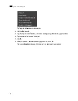
Page 407: ... 514 335 1614 E mail support miranda com Asia Office hours 9 00 a m 5 00 p m GMT 8 Telephone 852 2539 6987 Fax 852 2539 0804 E mail asiatech miranda com Europe Middle East Africa UK Office hours 9 00 a m 6 00 p m GMT Telephone 44 0 1491 820222 Fax 44 0 1491 820002 E mail eurotech miranda com China Telephone 86 10 5873 1814 E mail asiatech miranda com France Office hours 9 00 a m 5 00 p m GMT 1 Tel...

Reviews: