6
Kaleido-X16 Installation
Frame
1
Frame
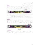
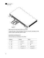
The Kaleido-X16 frame is 1 RU high. Input and output connectors are mounted on a connector panel on the
rear of the frame. The redundant power supply is installed in the front of the frame.
The front door can be opened to give access to the PSUs, CompactFlash, USB connector, and basic LEDs.
The Kaleido-X16 frame incorporates the following key sections:
• A rack-mountable mechanical framework (for mounting into a 19
-in
EIA rack)
• A removable door to cover and protect the front of the frame
• Redundant power supply
• Ventilation
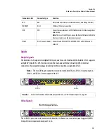
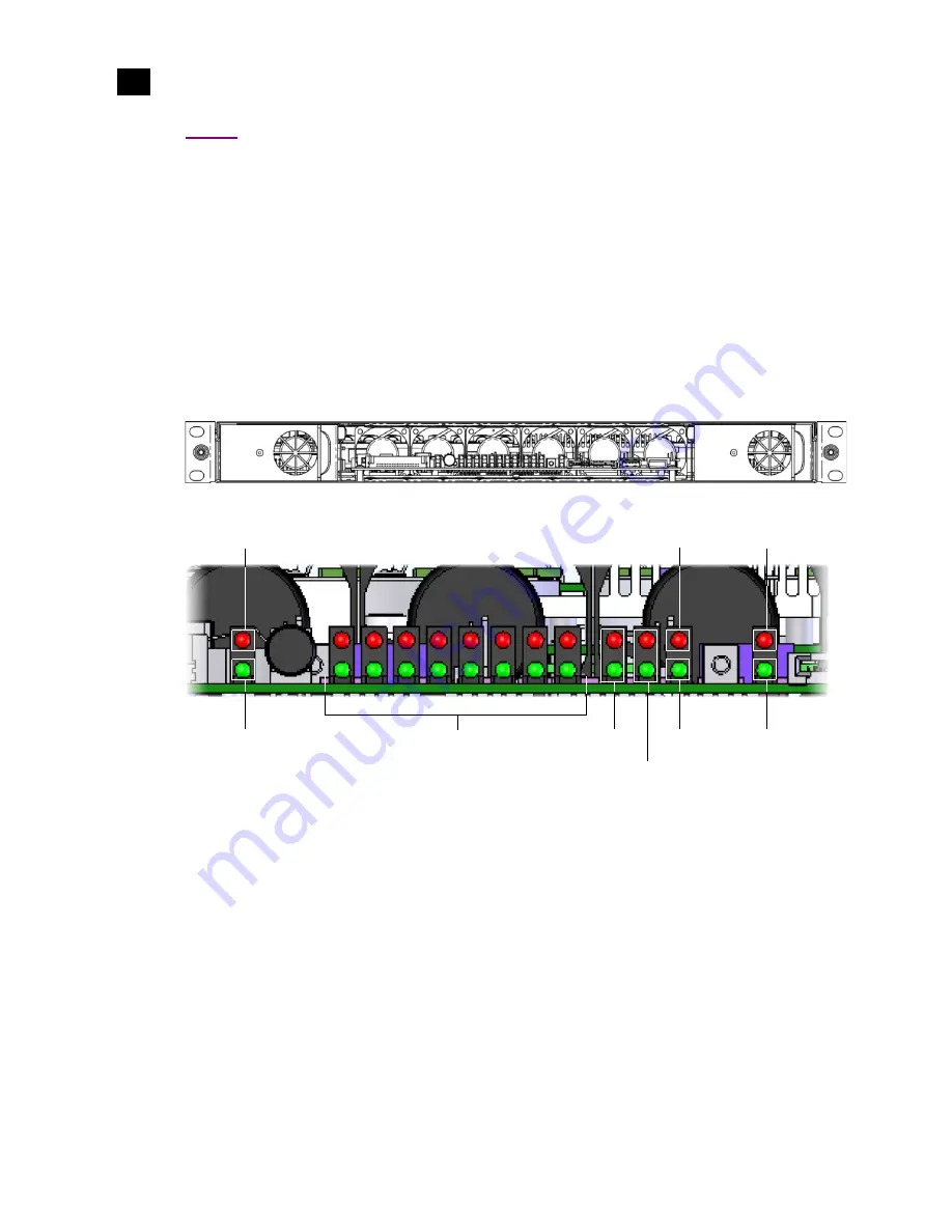
Front view of the Kaleido-X16 frame (PSUs installed; front cover removed)
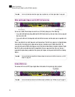
LEDs on the front of the frame (behind the door)
The LEDs on the front of the frame (behind the door) indicate the following conditions depending on their
color and whether they are blinking:
Video Inputs
LTC
DVI Inputs
SDTI
Reference Input
CPF Activity
CPU
Severity
General Status
Summary of Contents for Kaleido-X16
Page 4: ......
Page 32: ...26 Kaleido X16 Installation Replacing a Defective Power Supply 1 ...
Page 80: ...74 Specifications Physical Dimensions 3 ...
Page 82: ......


