Kaleido-X16
Hardware Description & Installation Manual
19
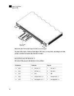
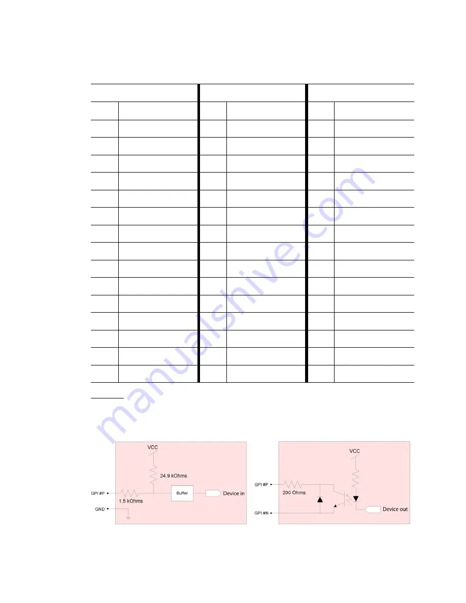
GPI Circuits
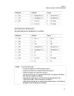
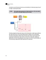
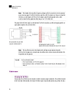
The individual GPI contacts are reconfigurable as either inputs or outputs. For interfacing purposes, the
input and output circuit configurations are as shown in the following diagrams:
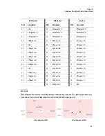
Bottom row
Middle row
Top row
Pin #
Description
Pin #
Description
Pin #
Description
31
GND
16
GPI Output P<1>
1
GPI Output N<1>
32
GPI Output P<2>
17
GPI Output N<2>
2
GPI Output P<3>
33
GPI Output N<3>
18
GPI Output P<4>
3
GPI Output N<4>
34
GPI Input <31>
19
GPI Input <32>
4
GPI Input <29>
35
GND
20
GPI Input <30>
5
GPI Input <27>
36
GPI Input <26>
21
GPI Input <28>
6
GPI Input <24>
37
GPI Input <23>
22
GPI Input <25>
7
GPI Input <21>
38
GPI Input <20>
23
GPI Input <22>
8
GPI Input <18>
39
GPI Input <16>
24
GPI Input <19>
9
GPI Input <15>
40
GPI Input <14>
25
GPI Input <17>
10
GPI Input <12>
41
GND
26
GPI Input <13>
11
GPI Input <10>
42
GPI Input <9>
27
GPI Input <11>
12
GPI Input <7>
43
GPI Input <6>
28
GPI Input <8>
13
GPI Input <4>
44
GPI Input <3>
29
GPI Input <5>
14
GPI Input <1>
30
GPI Input <2>
15
GND
GPI configured as INPUT
GPI configured as OUTPUT
Summary of Contents for Kaleido-X16
Page 4: ......
Page 32: ...26 Kaleido X16 Installation Replacing a Defective Power Supply 1 ...
Page 80: ...74 Specifications Physical Dimensions 3 ...
Page 82: ......


