GUIDE TO INSTALLATION AND OPERATION
12
| SPG-1801
•
LTC
– use the timecode connected to the LTC input on the rear panel
•
TC (URS)
– use the timecode included in the URS signal. generated by an REF-1801 card located in
slot 10 of the Densité frame
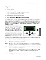
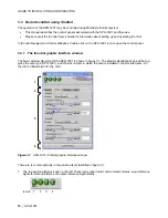
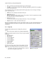
The current status of time code available at the SPG-1801 input is shown in the
LTC Status, VITC Status
and
TC (URS) Status
areas
•
Valid
(green icon): valid time code detected at the input
•
Phase error
(red icon):
SMPTE-12 specifies the phase relation between LTC and video. If the LTC received does not match
this alignment window, the card will flag this error.
•
Frame error
(red icon):
The time code must match the input reference frame rate. If not, an error is flagged.
•
Absent
(red icon): no time code detected at the input
Note: The error detection algorithm uses the current reference format. So, when using internal reference, all
information extracted from the input is out of phase, and the card may flag errors even if the timecode is
nominally OK.
3.3.3 Output
tab
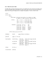
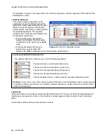
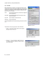
The Output tab provides resources to configure the output sync
signals.
•
Each of the two sync outputs can be configured independently.
Format
– the pulldown selects the format of the sync output. Available
choices are:
•
Black Burst 59.94
•
Black Burst 50
•
Tri-Level
1080i59.94
•
Tri-Level
1080i50
•
Tri-Level
720p59.94
•
Tri-Level
720p50
•
DARS
48
kHz
•
Word Clock 48 kHz
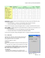
Note that not all of these output choices will be available at all times.
The output formats available depend on the format of the reference
input.
•
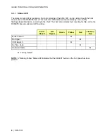
The following chart shows the relationship between reference
input format and available output formats.
Figure 3.3
Output tab


