75
TNC-5000 Telephone Network Controller Module
9.3
Connectors and Terminal Locations
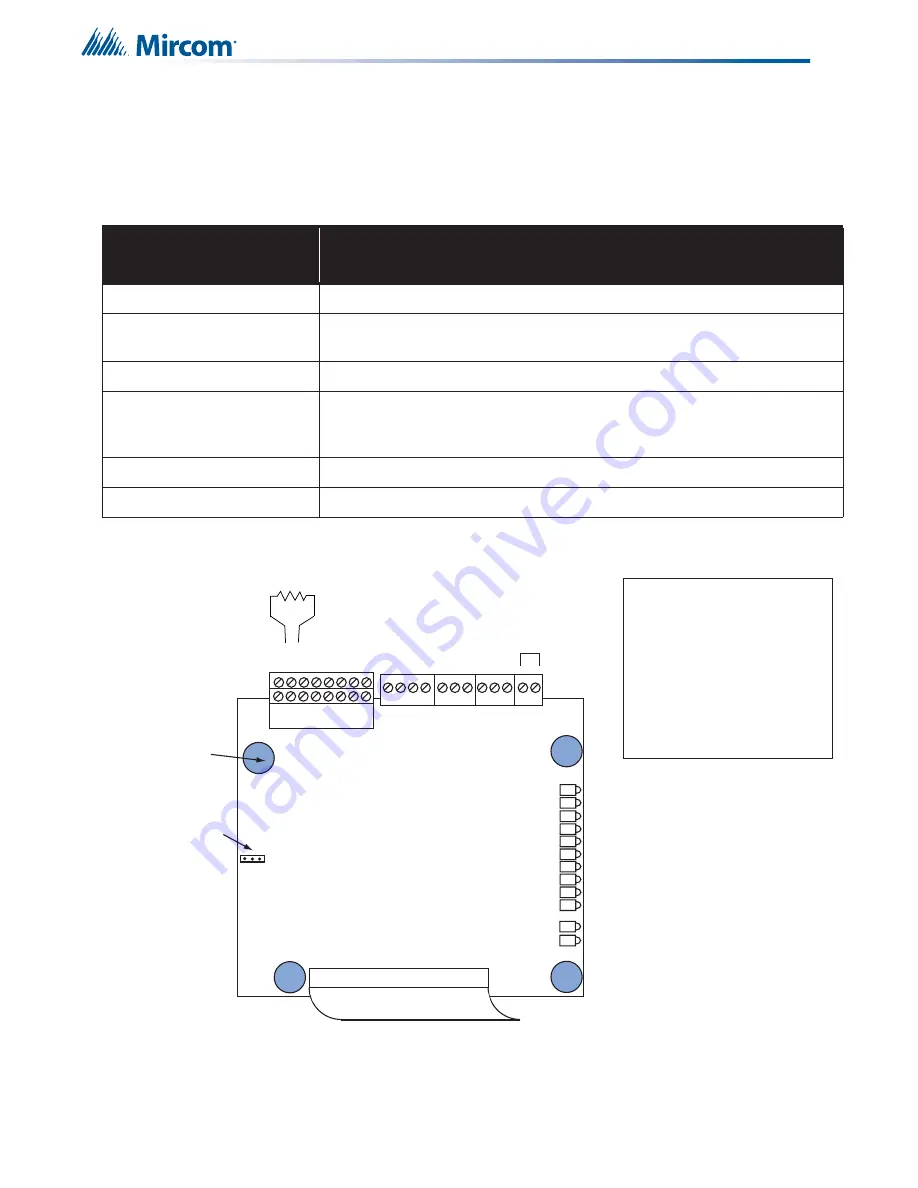
Table 14 below shows the cable connections and jumpers required and additional wiring. Refer to Figure 57 for
connector and terminal locations.
Figure 57 TNC-5000 Telephone Network Controller Board Layout
Table 14:
TNC-5000 Connectors and Terminals
TNC-5000
Connector and Terminals
Connects to
P10 Cable
P11 on the ANC-6000 Audio Network Controller Module.
Z1 Terminals
These two terminals are wired to the Master Telephone if used, otherwise to
any telephone zone.
Z2, Z3, Z4 and Z5 Terminals
These terminals are wired to telephone zones.
Telephone Bus In and Out
Terminals
Wire from previous TNC-5000 to next TNC-5000. Total cable resistance is 50
ohms maximum, 18 gauge twisted pair. Telephone Bus is power limited and
fully supervised
JW1
Jumper positions 1 and 2 if zone 1 is connected to a Master Telephone.
JW1
Jumper positions 2 and 3 if zone 1 is NOT connected to a Master Telephone.
Telephone Zones 1 to 4
are depluggable terminals.
A set of 8 terminals for Zone 3
and 4 above a set of 8 terminals
for Zone 1 and 2.
Z1
JW1
Z2
Z3
Z4
+ - S + - S
- - + + - - + +
- - + +
+ -
P10
Ribbon Cable connects to the
ANC-6000 Audio Network Controller
Module P11
Tel.
Bus
Out
Tel.
Bus
In
Ext.
Tel.
NOT
USED
Jumper in position
1 & 2 Zone 1 is
wired to a Master
Telephone
Jumper in position
2 & 3 Zone 1 is
wired as a regular
telephone zone
Mounting
Holes
Select Line 2
Select Line 3
Select Line 4
Select Line 5
Select Line 1
Trouble Line 1
Trouble Line 3
Trouble Line 4
Trouble Line 5
Status Bus Out
Status Bus In
Trouble Line 2
1
2
3
Z5
- - + + - - + +
E.O.L. 10KΩ
Five 10K
Ω
E.O.L. resistors come
installed on each of the telephone
zone terminal blocks.
Telephone Bus
Specifications:
15V, 50mA Maximum
Total cable resistance: 50
ohms max
18 gauge twisted pair wire
Telephone Bus is power-
limited and fully supervised
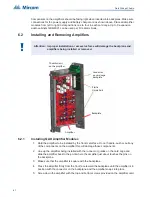
Summary of Contents for FX-MNS-6000
Page 2: ......


