90
TNC-5000 Telephone Network Controller Module
9.16.5
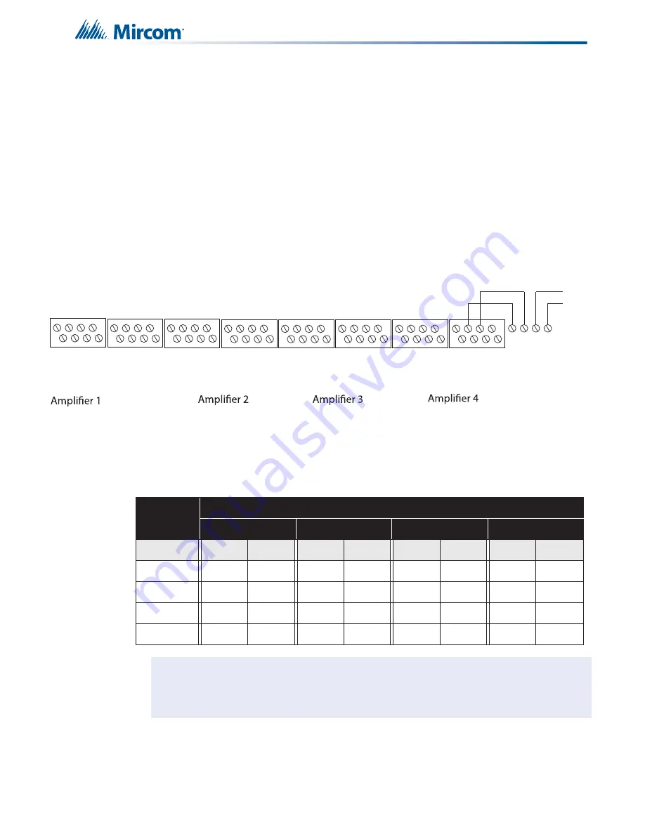
Backup Amplifier Wiring
Any amplifier may be designated (through configuration) as a backup amplifier per node when
backup is required. Use of 25V or 70V must be restricted to one or the other per node. The
backup amplifier can be any amplifier installed in any audio cabinet per each node.
The number of backup amplifiers is limited to one per node. Only the first failed amplifier gets
the backup. The backup amplifier is set up by configuration. Select one amplifier on a
backplate and it will be a backup for the other amplifier circuits on the QMB-6000. To backup
any other amplifiers on the next backplate, the designated Backup Amplifier must be wired A+
and A- to the + and - terminals of the Backup Bus Supervision Continuation terminals and the
other + and - terminals of this connector to the next backplate. The End of Line resistor for the
backup amplifier should be connected at the last backplate.
Table 16
Wiring Chart for 70V Speakers
Total
Power
Maximum Wiring Run To Last Device (ELR)
18AWG
16AWG
14AWG
12AWG
Watts
ft
m
ft
m
ft
m
ft
m
25
1740
531
2966
841
4399
1342
6995
2132
50
970
266
1383
421
2200
671
3497
1066
75
580
177
922
280
1466
447
2332
711
100
435
133
691
210
1100
335
1749
533
Notes for Wiring Charts:
For each speaker zone, select the total zone power. Distance
shown is calculated to the last speaker, based on the worst case with all speakers lumped
at the end. Calculation is base on a 1db power loss (20%) and a source of 70V or 25V.
B+
A+
A-
B-
1.2
1.1
B+
A+
A-
B-
1.4
1.3
B+
A+
A-
B-
2.2
2.1
B+
A+
A-
B-
2.4
2.3
B+
A+
A-
B-
3.2
3.1
B+
A+
A-
B-
3.4
3.3
B+
A+
A-
B-
4.2
4.1
B+
A+
A-
B-
4.4
4.3
- + - +
Wire the designated backup amplifier
to the Backup Bus terminals
Backup Bus
Supervision
Continuation
Terminals
Wire this to
the next
backup bus
continuation
terminals of
the next
backplane
i
Summary of Contents for FX-MNS-6000
Page 2: ......


