An external emergency stop circuit is recommended.
Before running the tool
Before starting the tool, check that the tool is mounted properly and ensure that the motor drive is installed
properly.
Motor drive overview
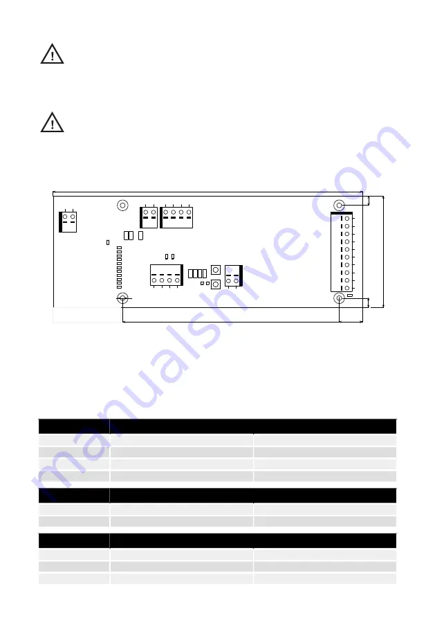
Motor drive PCB connectors, buttons, jumpers, indicators, mounting holes and dimensions
B
J
3
J
P1
3
J
P1
5
J4
D17
D21
NTC+
N
O
D26
D2
D18
D3
D19
D20
D23
D24
GND
J6
1
5
V
A
D
I4
GND
D
I2
J
P3
J
P4
J5
D
I1
D
4
J
P2
J
P1
S2
S1
GND
155
D36
P+
C+
P-
GND
NTC-
7
2
D22
D25
J
P1
2
G
N
D
J1
D
3
0
D
1
4
J2
C-
PhaseB
C
O
M
D
I3
200
48V
15
6
PhaseA
PhaseC
6
ø 3,20
D
2
9
Dimensions specified in
millimeters.
The motor drive PCB comes mounted in a DIN-rail holder that can be attached to a standard 35 x 7.5mm EN50022 DIN-rail,
but the motor drive PCB can be removed from this holder and mounted using the mounting holes instead. If the mounting
holes are used, then it is recommended to use 20 mm metal standoffs and 10 mm M3 screws when mounting the motor
drive PCB.
It is recommended to use 10 mm ferrules with plastic sleeve for each wire that is attached to any of the connectors. The
wires can then easily be pushed into the connectors and released with the help of a small flat-head screwdriver (3.5 mm
blade width, 0.6 mm blade thickness).
Connector description
Description
PIN
Connector
GND
GND
J1
Modbus RTU RS-485 (A)
A
J1
Modbus RTU RS-485 (B)
B
J1
GND
GND
J1
Description
PIN
Connector
GND
GND
J2
48 VDC input
48V
J2
Description
PIN
Connector
P+
P+
J3
C+
C+
J3
C-
C-
J3
6
en (original)


