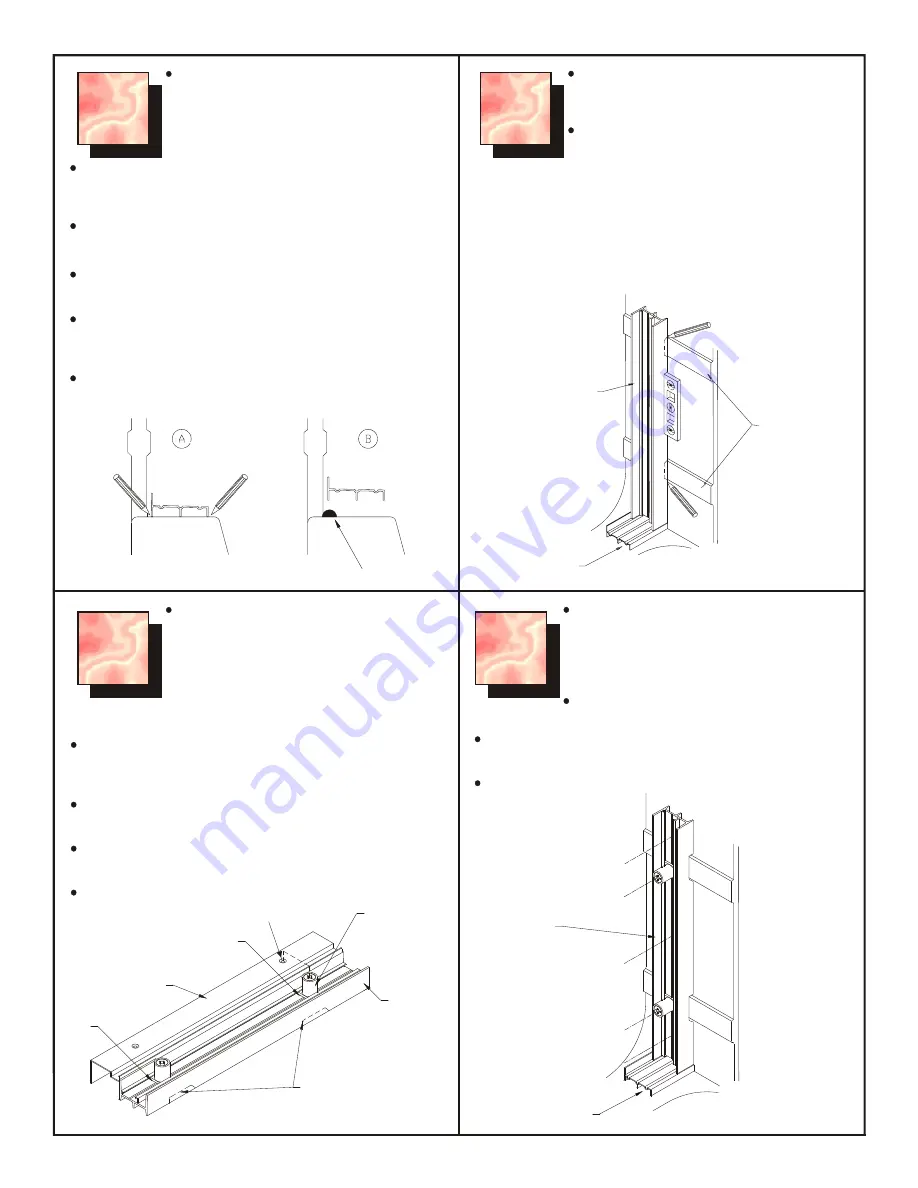
background image

5

3

3

1

1

2

2

Position the plastic jambs against the wall 
according to the position as shown ensuring 
that the flexible fins are against the tub wall.

Plumb with level and pencil mark as shown.

4

4

 (Note: Not applicable for M36, M37, M41  & 360 installation.

Reposition the plastic jamb and drill three 1/8” 
(3 mm) holes through the plastic wall jamb and 
shower wall. The holes should be spaced 
along the jamb and drilled as perpendicular to 
the wall as possible.

Check that the adjusting blocks are in the 
marked position.

Carve out, with a knife the three fins on the 
rear side of each plastic jamb in order that it 
may fit the contour of the raised bands of the 
acrylic tub/shower or shower stall.

(Not applicable to fiberglass products, 
model #s: 314836AC, 374835A, 326032A,   
376032B, M41 & 360 Series door 
installation).

Slide the adjustment blocks (T-12) into each end of the plastic 
jambs (T-7). Be sure that the adjustment screws are all the way 
into the adjustment blocks.

Lay one plastic jamb (T-7) and an aluminum wall jamb (T-2) 
side by side on a flat surface.

Align the adjusting blocks (T-12) with the prepunched holes in 
the aluminum jamb. Mark the location of the adjusting blocks.

Repeat with the other plastic jamb and aluminum wall jamb.

Depending on the location of the shower head, 
determine which way to position the 
interchangeable panels (T-4, T-5, T-6), wall 
jambs (T-2) and plastic jambs (T-7). See 
Figures 1, 2, 3 or 4.

NOTE:

 Only for the M160/M360 and 360 Series door   

installation: measure the wall opening at the tub rim and cut the 
sill (T-3) to suit the full width of the tub.

Place the sill (T-3) on the rim of the tub/shower or shower stall, 
in line and closer to the inner edge of the rim.

Draw a pencil line (A) along the outside and inside of the sill, 
then remove the sill.

Apply a bead of silicone caulking(B) along the outside pencil 
line. Press the sill onto the base in the original position using 
the inside pencil line as a guide.

Remove excess silicone.

Drill a 1/8” (3 mm) hole through each adjusting block, the 
plastic jamb and the shower wall.

Drill the holes as perpendicular as possible.

PENCIL

PENCIL

SILICONE

T-3
SILL

T-7
PLASTIC
JAMB

OUTSIDE

RAISED 
BANDS

INSIDE TUB

PENCIL MARK

T-2
WALL JAMB

PENCIL MARK

T-12
ADJUSTMENT
BLOCK

T-7 PLASTIC
 JAMB

CARVE OUT

DRILL

DRILL

DRILL

DRILL

DRILL

T-3
SILL

OUTSIDE

INSIDE TUB

T-7
PLASTIC 
JAMB

LEVEL

PREPUNCHED HOLE

Summary of Contents for Miroglide 360 Series

Page 1: ...which is one of our main company objectives Although our employees take great pride and special care regarding product packaging and shipment problems do occur Should you have any problem regarding p...

Page 2: ...ile GENERAL CUSTOMER INFORMATION Never use scouring powder pads or sharp instruments on the metal framing or glass panels An occasional cleaning with a mild liquid detergent or cleaner such as a windo...

Page 3: ...3 FIG 2 SHOWER HEAD LEFT FIG 1 SHOWER HEAD RIGHT EXPLODED VIEW DOOR MODELS M33 M34 M35 M38 M39 M40...

Page 4: ...FIG 4 SHOWER HEAD LEFT FIG 3 SHOWER HEAD RIGHT 4 EXPLODED VIEW DOOR MODELS M36 M37 M41 360 NOTE NO WALL ANCHOR INSTALLATION FOR M41...

Page 5: ...12 with the prepunched holes in the aluminum jamb Mark the location of the adjusting blocks Repeat with the other plastic jamb and aluminum wall jamb Depending on the location of the shower head dete...

Page 6: ...rews through the adjusting blocks yet Repeat with the other plastic wall jamb 6 T 8 8 X 1 1 2 38 mm SCREW T 7 PLASTIC JAMB OUTSIDE T 3 SILL INSIDE TUB T 2 WALL JAMB T 7 PLASTIC JAMB PLUMB LEVEL T 9 8...

Page 7: ...cks on the sill The height of the panels and the operation of the skates may be adjusted by selecting different holes in the wheel bracket If the skates are binding in the track the lower holes should...

Page 8: ...the towel bar T 15 between the brackets and fasten with the two 6 X 1 2 13 mm screws T 13 We want you to be completely satisfied with our products and service If you have any comments or suggestions p...

Page 9: ...ectifs de notre soci t Bien que nos employ s se fassent un devoir de prendre des pr cautions sp ciales en ce qui concerne le conditionnement et l exp dition de nos produits il arrive que des probl mes...

Page 10: ...de baignoire la silicone Niveau avec bulle verticale Pointeau rep re ou outil semblable Scie m taux lame fiine 32 dents Bo te onglet ou querre de menuisier Lime douce RENSEIGNEMENT G N RAUX POUR LE C...

Page 11: ...3 FIG 1 T TE DE DOUCHE DROITE FIG 2 T TE DE DOUCHE GAUCHE La Porte explos e de Vue Mod le M33 M34 M35 M38 M39 et M40...

Page 12: ...4 La Porte explos e de Vue Mod le M36 M37 M41 et 360 Prendre note Aucune installation d ancre de mur pour le mod le M41 FIG 3 T TE DE DOUCHE DROITE FIG 4 T TE DE DOUCHE GAUCHE...

Page 13: ...astique T 7 et un chambranle mural en aluminium T 2 c te c te sur une surface plane Aligner les cales de r glage T 12 avec les trous d j perc s dans le chambranle d aluminium Marquer l emplacement des...

Page 14: ...l autre chambranle mural en plastique 6 6 6 Guilder chaque chambranle mural T 2 sur le chambranle en plastique et v rifier si l ensemble est bien d aplomb et utilisant un niveau Si un r glage est n c...

Page 15: ...rous dans le support de roulette Si les patins se coincent dans le rail il faudra choisir des trous plus bas Si la porte a tendance sortir du rail on devra utiliser les trous plus haut LA NOTE Seuleme...

Page 16: ...acer le porte serviette T 15 entre les supports et serrer les deux vis n 6 x po 13 mm Nous voulons que vous soyez compl ment satisfait de nos produits et services Si vous avez de commentaires ou sugge...

Reviews: