English –
13
English
04.
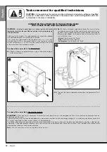
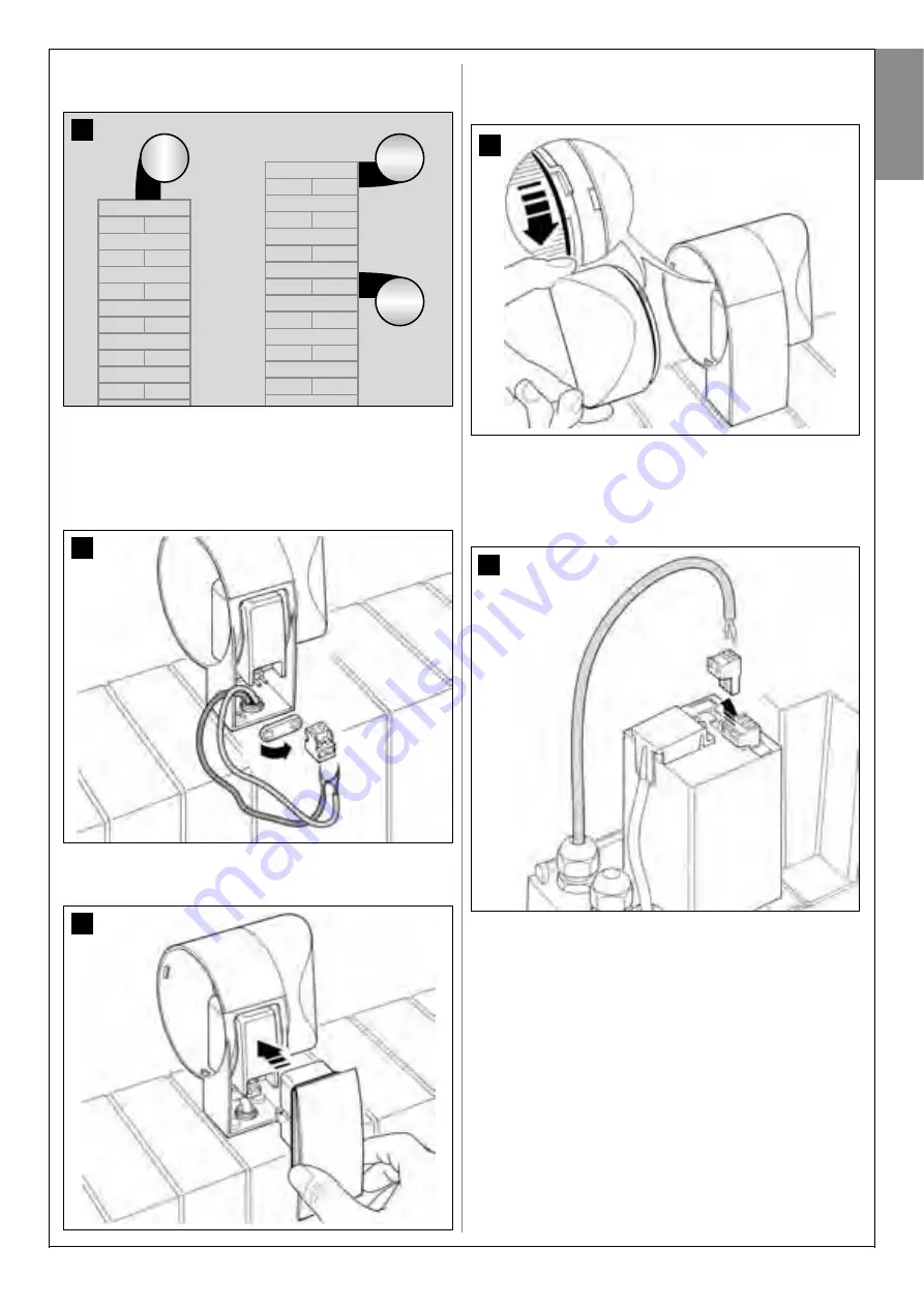
Fig. 20:
CAUTION!
- Do not mount the product in positions other than
those specified.
05.
Fix the body of the flashing light to the wall with the relative screws,
routing the cables through the prepared hole.
06.
Fig. 21:
a)
Connect the wires of the two cables and secure on the terminal
board
b)
Lock the cable by means of the relative cable clamp.
07.
Fig. 22:
Insert the cap of the flashing unit in its seat until the tabs click in
place.
21
20
22
08.
Fig. 23:
Refit the transparent cover in its seat and turn clockwise, taking care
that the serrated section engages with those on the flashing light
body.
09.
Fig. 24:
a)
On the gearmotor control unit, remove the BUS connection termi-
nal board from its seat to enable loosening of the 2 terminal screws.
b)
Proceed with connection of the cable wires, observing the sym-
bols on the terminal board and refit the latter in its seat.
c)
Then tighten the cable clamp to secure the cable to the gearmotor.
23
24


